
Page 37 - Process simulation and control using Aspen
P. 37
30 PROCESS SIMULATION AND CONTROL USING ASPEN
Creating flowsheet
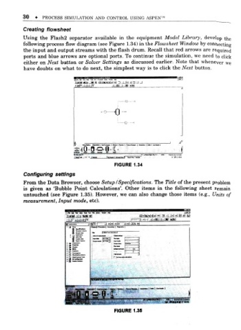
Using the Flash2 separator available in the equipment Model Library, develop the
following process flow diagram (see Figure 1.34) in the Flowsheet Window by connecting
the input and output streams with the flash drum. Recall that red arrows are required
ports and blue arrows are optional ports. To continue the simulation, we need to click
either on Next button or Solver Settings as discussed earlier. Note that whenever we
have doubts on what to do next, the simplest way is to click the Next button.
rjafn ..|-|..|. {k jl .15)1 I gl *w
.
0
o
o-e-oi-ir-
mm 1 _ 2£
£S-| »... >
FIGURE 1.34
r
Configuing settings
From the Data Browser, choose Setup ISpecifications. The Title of the present problem
is given as 'Bubble Point Calculations'. Other items in the following sheet remain
untouched (see Figure 1.35). However, we can also change those items (e.g., Units of
measurement. Input mode, etc).
3 -.1 ,b. i -. m -\u
-
gag i 3 abi 3 »l alai
-
ij
, u m
it »
« "'E E3
FIGURE 1.35