
Page 44 - Process simulation and control using Aspen
P. 44
INTRODUCTION AND STEPWISE ASPEN PLUS SIMULATION 37
Subsequently, dick OK when the Aspen Plus engine window pops up.
Creating flowsheet
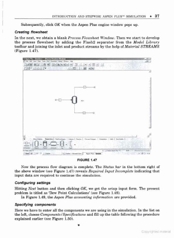
In the next, we obtain a blank Process Flowsheet Window. Then we start to develop
the process flowsheet by adding the Flash2 separator from the Model Library
toolbar and joining the inlet and product streams by the help of Material STREAMS
(Figure 1.47).
gjfffc i« Dm > Ha-w- Ifca* . .iffi J
3
- H c-
0 St*
- CD c
if
±
itftLWfS n>rJ f* i c-*. --3 s«.-
mt| » -i>w. |>-icj- i.«tanwr|| - # i
FIGURE 1.47
Now the process flow diagram is complete. The Status bar in the bottom right of
the above window (see Figure 1.47) reveals Required Input Incomplete indicating that
input data are required to continue the simulation.
Configuring settings
Hitting Next button and then clicking OK, we get the setup input form. The present
'
problem is titled as Dew Point Calculations' (see Figure 1.48).
In Figure 1.49, the Aspen Plus accounting information are provided.
Specifying components
Here we have to enter all the components we are using in the simulation. In the list on
f
the let, choose Components /Specifications and fill up the table following the procedure
explained earlier (see Figure 1.50).
Copyrighted malenal