
Page 63 - Process simulation and control using Aspen
P. 63
56 4 PROCESS SIMULATION AND CONTROL USING ASPEN
jzj
I M I I I lAl I I I - I
[5'.f»**-«i "v.* (Ma
j " *-** , /.r . - - ( 'o-.
t
JV--- *.j m . , _
j ' jJ. mo; Mil E-v v 'Mi 3 'th B«M
r . jw*-N«a»et« SkwtrM
t
W
j .j--jc-r; ] f.-S- -.r 3 C j n-V; j «' if!: VV.
.
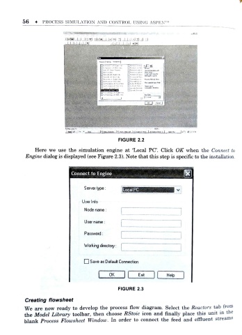
FIGURE 2.2
Here we use the simulation engine at 'Local PC. Click OK when the Connect to
f
Engine dialog is displayed (see Figure 2.3). Note that this step is speciic to the installation .
Connect to Engine
Server type: Local PC
User Info
Node name :
User name:
Password:
Working directory:
O Save as Default Connection
OK Exit Help
FIGURE 2.3
Creating flowsheet
We are now ready to develop the process flow diagram. Select the Reactors tab from
the Model Library toolbar, then choose RStoic icon and finally place this un it in the
f
blank Process Flowsheet Window. In order to connect the feed and efluent s treams