Page 88 - Process simulation and control using Aspen
P. 88

80       PROCESS SIMULATION AND CONTROL USING ASPEN          TM

    Creating flowsheet
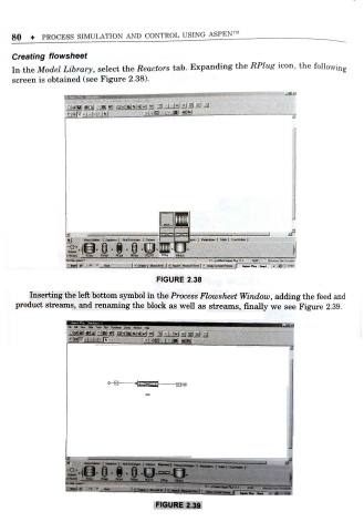
    In the Model Library, select the Reactors tab. Expanding      the RPlug icon, the followin g
    screen is obtained (see Figure 2.38).


                                             li,-1?-:-:?-- IM

                   Uj                      _
                       jS's - s - § o
                          t
                   SIftEAMS  '  RSoc  flY»fc)  W»J  RCte  RCSTR  RBtfd<


                                            FIGURE 2.38
         Inserting the left bottom symbol in the Process Flowsheet Window adding the feed and
                                                                           ,
     product streams, and renaming the block as well as streams, finally we see Figure 2.39.


                    Be £* *>  &M ro* ftj>  Uonn WnSo* H*
                     t
                    r|tF..U|-. -nr        Nsi|--..| -MBi  IN


                                      >|[T><rr|  h~o


                   I*   -****** | f«M». t hmI- mw | c*-« iu««« I rM..1,o,  i  1  , '
                                                     _
                       iS- SSI Gj                q.
                       -
                                                  f
                   S'W  ' BS*»  FTiMd  ftc  nstfa.  HCSTB  flfy ,  Ttj T
                                            FIGURE 2 .39
   83   84   85   86   87   88   89   90   91   92   93