
Page 263 - Programming Microcontrollers in C
P. 263
248 Chapter 5 Programming Large 8-Bit Systems
OC1M.OC1M5=ON; /* couple OC1 to OC3 */
OC1D.OC1D5=ON; /* turn on OC3 when OC1 occurs */
TCTL1.OL3=ON; /* toggle OC3 when OC3 occurs */
PACTL.DDRA7=ON; /* make OC1 an output to PA7 */
TOC1=TCNT+period; /* set OC1 to the period */
TOC3=TOC1+time_on; /* set OC3 to the time on */
FOREVER
{
if(TFLG1&OC1F)
{
TFLG1=OC1F; /* reset OC1 interrupt flag */
TOC1+=period;
OC1D.OC1D7 ^=ON; /* toggle the output
Compare 1 bit */
}
if(TFLG1&OC3F)
{
TFLG1=OC3F;/*reset OC3 interrupt flag */
TOC3=TOC1+time_on;
}
}
}
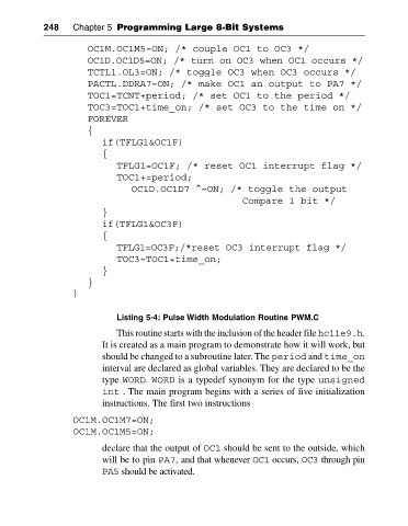
Listing 5-4: Pulse Width Modulation Routine PWM.C
This routine starts with the inclusion of the header file hc11e9.h.
It is created as a main program to demonstrate how it will work, but
should be changed to a subroutine later. The period and time_on
interval are declared as global variables. They are declared to be the
type WORD. WORD is a typedef synonym for the type unsigned
int . The main program begins with a series of five initialization
instructions. The first two instructions
OC1M.OC1M7=ON;
OC1M.OC1M5=ON;
declare that the output of OC1 should be sent to the outside, which
will be to pin PA7, and that whenever OC1 occurs, OC3 through pin
PA5 should be activated.