
Page 316 - Programming Microcontrollers in C
P. 316
A Pulse Width Modulation Program 301
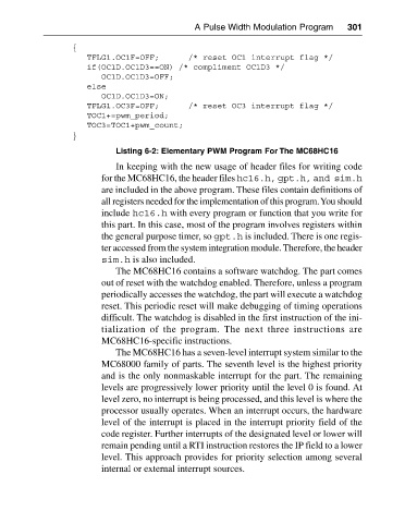
{
TFLG1.OC1F=OFF; /* reset OC1 interrupt flag */
if(OC1D.OC1D3==ON) /* compliment OC1D3 */
OC1D.OC1D3=OFF;
else
OC1D.OC1D3=ON;
TFLG1.OC3F=OFF; /* reset OC3 interrupt flag */
TOC1+=pwm_period;
TOC3=TOC1+pwm_count;
}
Listing 6-2: Elementary PWM Program For The MC68HC16
In keeping with the new usage of header files for writing code
for the MC68HC16, the header files hc16.h, gpt.h, and sim.h
are included in the above program. These files contain definitions of
all registers needed for the implementation of this program. You should
include hc16.h with every program or function that you write for
this part. In this case, most of the program involves registers within
the general purpose timer, so gpt.h is included. There is one regis
ter accessed from the system integration module. Therefore, the header
sim.h is also included.
The MC68HC16 contains a software watchdog. The part comes
out of reset with the watchdog enabled. Therefore, unless a program
periodically accesses the watchdog, the part will execute a watchdog
reset. This periodic reset will make debugging of timing operations
difficult. The watchdog is disabled in the first instruction of the ini
tialization of the program. The next three instructions are
MC68HC16-specific instructions.
The MC68HC16 has a seven-level interrupt system similar to the
MC68000 family of parts. The seventh level is the highest priority
and is the only nonmaskable interrupt for the part. The remaining
levels are progressively lower priority until the level 0 is found. At
level zero, no interrupt is being processed, and this level is where the
processor usually operates. When an interrupt occurs, the hardware
level of the interrupt is placed in the interrupt priority field of the
code register. Further interrupts of the designated level or lower will
remain pending until a RTI instruction restores the IP field to a lower
level. This approach provides for priority selection among several
internal or external interrupt sources.