
Page 98 - Programming the Photon Getting Started With the Internet of Things
P. 98
When you connect the switch to your Photon, you need a pull-down resistor to ensure
that the input is connected to ground on the Photon board. Table 5.1 shows the
components that you will need to use in this example.
Schematic Reference Description Appendix
M1 Photon board M1
400-point breadboard H1
Jumper wires (M-M) H2
R1 10-K resistor R3
S1 Push-button switch (tactile) H6
Table 5.1 Components and Hardware
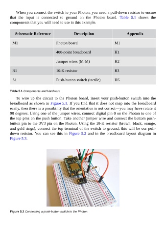
To wire up the circuit to the Photon board, insert your push-button switch into the
breadboard as shown in Figure 5.1. If you find that it does not snap into the breadboard
easily, then there is a possibility that the orientation is not correct—you may have rotate it
90 degrees. Using one of the jumper wires, connect digital pin 0 on the Photon to one of
the top pins on the push button. Take another jumper wire and connect the bottom push-
button pin to the 3V3 pin on the Photon. Using the 10-K resistor (brown, black, orange,
and gold rings), connect the top terminal of the switch to ground; this will be our pull-
down resistor. You can see this in Figure 5.2 and in the breadboard layout diagram in
Figure 5.3.
Figure 5.2 Connecting a push-button switch to the Photon.