
Page 101 - Programming the Raspberry Pi Getting Started with Python
P. 101
Both the Pi Cobbler and the display modules from Adafruit come as kits that must be soldered
together before they can be used. Both are fairly easy to solder, and detailed step-by-step instructions
for building them can be found on the Adafruit website. Each module has pins that just push into the
holes on the breadboard.
The display has just four pins (VCC, GND, SDA, and SCL) when it is plugged into the breadboard;
align it so that the VCC pin is on row 1 of the breadboard.
The Cobbler has 26 pins, but we will only be using a few of them. It should be inserted at the other
end of the breadboard, or at least far enough away so that none of the pins overlap with the same rows
as the display. The Cobbler socket has a cutout on one side to ensure that the ribbon cable can only be
inserted one way. This cutout should be toward the top of the breadboard, as shown in Figure 10-2.
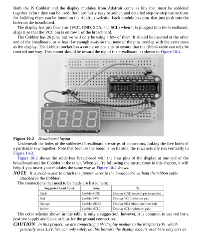
Figure 10-2 Breadboard layout
Underneath the holes of the solderless breadboard are strips of connectors, linking the five holes of
a particular row together. Note that because the board is on its side, the rows actually run vertically in
Figure 10-2.
Figure 10-2 shows the solderless breadboard with the four pins of the display at one end of the
breadboard and the Cobbler at the other. When you’re following the instructions in this chapter, it will
help if you insert your modules the same way as Figure 10-2 shows.
NOTE It is much easier to attach the jumper wires to the breadboard without the ribbon cable
attached to the Cobbler.
The connections that need to be made are listed here:
The color scheme shown in this table is only a suggestion; however, it is common to use red for a
positive supply and black or blue for the ground connection.
CAUTION In this project, we are connecting a 5V display module to the Raspberry Pi, which
generally uses 3.3V. We can only safely do this because the display module used here only acts as