
Page 177 - Radar Technology Encyclopedia
P. 177
167 error model error, multipath
where m , and s are mean values and rms errors for the sys-
xi
xi
tematic component (i = 1), the slowly fluctuating component Target Target
(i = 2), and the rapidly fluctuating component (i = 3), h(t) is a q t Horizon q t >2 b 0 Horizon
i
reference random function with zero mean value, unity vari-
ance, and specified correlation function K (t). Typically, -q t Image of Image of ~
xi
target, r = 0.7
K (t) = 1, K (t) is defined by the slow fluctuations, and target q= 4b 0 Glistening s
x2
x1
K (t) = d(t) (i.e., this portion of the model describes delta- (a) surface,
x3
~
correlated noise error (uncorrelated from sample to sample)). (b) r = 0.25
d
If there are M independent components that originate
Target
each ith error constituent part,
q t >2 b 0
M Horizon q t < 2 b 0 Target
m = å m = m Intense scattering
x i x im ij ,
near horizon
m = 1 q= 4b 0 Glistening q= q t +2b 0
de
surface, Glistening
~
M r = 0.4 surface, r = 0.4
~
d
2 d
s = å s = s
x i x im i
q = 4 q b (c) (d)
da
0
t
m = 1
and a convenient expression to simulate the error at the time
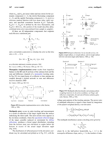
Figure E10 Multipath reflections for (a) smooth surface, (b)
nDt, n = 0, ..., N, is
slightly rough surface, (c) rough surface, and (d) rough surface
3 with low-elevation target (after Barton, 1969, p. 150).
×
x n Dt ) = å [ m + s h n Dt )× i ( × ]
(
i
i
Elevation,q Elevation, q
i = 1
as a discrete stationary random process. SAL Reflection density Antenna voltage gain
Ref.: Leonov (1990), p. 198; Barton (1988), pp. 505–512. 2
Tracking axis
q t A t
Monopulse (implementation) error results from imperfect
balance in the RF and IF portions of the antenna feed and the q d A (v) S
2
sum and difference channels of a monopulse tracking radar. 0 Horizon
In Fig. E9, two input horns of a reflector or lens antenna are D
coupled through a hybrid network to sum and difference
2
receiver channels. DKB q 0 r s0
Ref.: Barton (1969), pp. 208–210.
h
d
A A + Bd
Signal 1 1 + j0 S = A + Bd 1
A (a) (b)
e = Re (D/S) Figure E11 Multipath reflection density and antenna pattern
.
.
weighting functions in elevation coordinate. (a) Target and
reflection components, (b) sum and difference antenna gains
Signal
B d 2 (after Barton, 1988, p. 520).
Bd 1 A - Bd 1 D= (A - Bd )d 2
1
voltage gain patterns of the tracking antenna. The power ratio
Input horns Comparator Receivers Error detector
of multipath reflection to signal is then found by integration
of the pattern-weighted density over elevation:
Figure E9 Monopulse implementation errors (after Barton,
1969, p. 208).
I D 1 2 2
A q()rq()hDq() q
----- = ------ 2 ò r 0 d d
Multipath error occurs in radar tracking and measurement S A
t q
as a result of reflection of the target signal from the surface
2 2 2 2 2
(
(
(
(
underlying the direct path. The most serious error appears in + A q( 0 )rq )Dq ) A q ) A v () q)
d
0
r
0
r
d
0
the elevation coordinate, where the specularly reflected image
of the target, possibly replaced or surrounded by diffuse The multipath interference causes a tracking error given by
reflections, produces a broad signal distribution extending q
e
from the horizon (near zero elevation) to angles below the s = ------------------------------
q
S
æö
horizon in excess of the actual target elevation angle k 2 ----- n
m I èø e
(Fig. E10). D
The distribution of reflected power in the elevation coor- where q is the half-power beamwidth, k m » 1.5 the
is
e
dinate may be calculated and plotted as in Fig. E11, with the monopulse difference slope, and n » 1 is the number of inde-
e