
Page 181 - Radar Technology Encyclopedia
P. 181
171 error, range error, scintillation
1
s = -----------------------
A
(
2 SN )
¤
SAL
Ref.: Skolnik (1962), p. 463; Shirman (1970), p. 177.
Table E7
Range Error Components
Error class Bias components Noise components
Radar- Zero range setting; Thermal noise; multi-
dependent range discriminator path; clutter; jam-
tracking shift; receiver delay ming; variation in
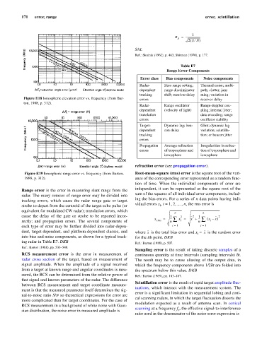
Figure E18 Ionospheric elevation error vs. frequency (from Bar- errors receiver delay
ton, 1988, p. 312).
Radar- Range oscillator Range-doppler cou-
dependent (velocity of light) pling; internal jitter;
translation data encoding; range
errors oscillator stability
Target- Dynamic lag; bea- Glint; dynamic lag
dependent con delay variation; scintilla-
tracking tion; or beacon jitter
errors
Propagation Average refraction Irregularities in refrac-
errors of troposphere and tion of troposphere and
ionosphere ionosphere
refraction error (see propagation error).
Figure E19 Ionospheric range error vs. frequency (from Barton, Root-mean-square (rms) error is the square root of the vari-
1988, p. 312). ance of the corresponding error represented as a random func-
tion of time. When the individual components of error are
independent, it can be represented as the square root of the
Range error is the error in measuring slant range from the
sum of the squares of all individual error components, includ-
radar. The many sources of range error may be divided into
ing the bias errors. For a series of n data points having indi-
tracking errors, which cause the radar range gate or target
vidual errors x , i = 1, 2, ... , n, the rms error is
strobe to depart from the centroid of the target echo pulse (or i
equivalent for modulated CW radar); translation errors, which
n n
cause the delay of the gate or strobe to be reported incor- 1 2 2 1 2
x = --- å x = x + --- å ( x – x )
rectly; and propagation errors. The several components of rms n i n i
each type of error may be further divided into radar-depen- i = 1 i = 1
dent, target-dependent, and platform-dependent classes, and where is the total bias error and x - is the random error
x
x
i
into bias and noise components, as shown for a typical track- for the ith point. DKB
ing radar in Table E7. DKB Ref.: Barton (1988), p. 507.
Ref.: Barton (1988), pp. 533–548.
Sampling error is the result of taking discrete samples of a
RCS measurement error is the error in measurement of continuous quantity at time intervals (sampling intervals) dt.
radar cross section of the target, based on measurement of The result may be to cause aliasing of the output data, in
signal amplitude. When the amplitude of a signal received which the frequency components above 1/2dt are folded into
from a target at known range and angular coordinates is mea- the spectrum below this value. DKB
sured, the RCS can be determined from the relative power of Ref.: Barton (1969), pp. 183–187.
that signal and known parameters of the radar. The difference
Scintillation error is the result of rapid target amplitude fluc-
between RCS measurement and target coordinate measure-
tuations, which interact with the measurement system. The
ment is that the measured parameter itself determines the sig-
error is a significant limitation in sequential lobing and coni-
nal-to-noise ratio S/N so theoretical expressions for error are
cal scanning radars, in which the target fluctuation distorts the
more complicated than for target coordinates. For the case of
modulation expected as a result of antenna scan. In conical
RCS measurement in a background of white noise with Gaus-
scanning at a frequency f , the effective signal-to-interference
sian distribution, the noise error in measured amplitude is s
ratio used in the denominator of the noise error expression is