
Page 185 - Radar Technology Encyclopedia
P. 185
175 FANTASTRON feed, beam-forming network
FARADAY matrix (Fig. F3). These networks are also called beam-form-
ing matrices.
The Faraday constant is the angle of rotation of the polariza-
Radiating elements Directional
tion plane per unit path length, under the conditions of linear
couplers
polarized wave propagation in a magnetized ferrite. The typi- Beam
1
cal notation is
Beam
2
we
R = ----------( m + a– m – a )
f
2 Beam
3
where w = 2pf, f = frequency, e = dielectric constant, Beam
4
m = magnetic permeability, and a = the component of the
magnetic permeability tensor. AIL Terminations
Ref.: Nikol’skiy (1964), p. 184.
The Faraday rotation effect is the phenomenon of the rota- Figure F2 Blass multiple-beam-forming matrix.
tion of the plane of polarization of a linearly polarized wave
Radiating elements
when it is longitudinally (parallel to the external magnetic
field) propagated in a gyrotropic medium. This is explained
by the difference in the phase speeds of normal waves with
circular polarization when a linearly polarized wave is placed
Hybrids * units of phase shift are
on them. p /8 radians
The Faraday effect occurs when radio waves with fre-
2* 2* 2* 2*
quencies less than 3 GHz propagate in the ionosphere. It has
widespread usage in ferrite microwave units with longitudi-
3* 1* 1* 3*
nally magnetized ferrites (isolators, circulators, and phase
shifters). IAM
Ref.: Nikol'skiy (1964), p. 186; Berkowitz (1965), p. 360; Kravtsov (1983),
Beam ports
p. 81; Sazonov (1981), p. 264.
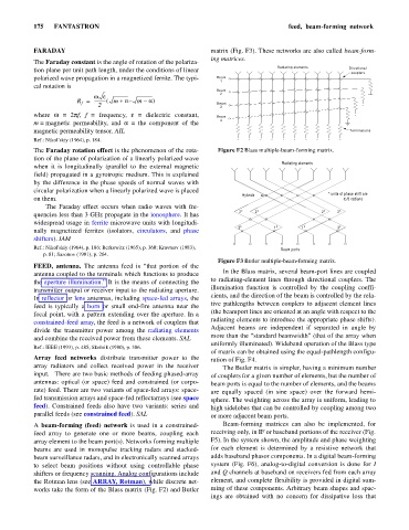
Figure F3 Butler multiple-beam-forming matrix.
FEED, antenna. The antenna feed is “that portion of the
In the Blass matrix, several beam-port lines are coupled
antenna coupled to the terminals which functions to produce
to radiating-element lines through directional couplers. The
the aperture illumination.” It is the means of connecting the
illumination function is controlled by the coupling coeffi-
transmitter output or receiver input to the radiating aperture.
cients, and the direction of the beam is controlled by the rela-
In reflector or lens antennas, including space-fed arrays, the
tive pathlengths between couplers to adjacent element lines
feed is typically a horn or small end-fire antenna near the
(the beamport lines are oriented at an angle with respect to the
focal point, with a pattern extending over the aperture. In a
radiating elements to introduce the appropriate phase shifts).
constrained-feed array, the feed is a network of couplers that
Adjacent beams are independent if separated in angle by
divide the transmitter power among the radiating elements
more than the “standard beamwidth” (that of the array when
and combine the received power from these elements. SAL
uniformly illuminated). Wideband operation of the Blass type
Ref.: IEEE (1993), p. 485; Skolnik (1980), p. 306.
of matrix can be obtained using the equal-pathlength configu-
Array feed networks distribute transmitter power to the ration of Fig. F4.
array radiators and collect received power in the receiver The Butler matrix is simpler, having a minimum number
input. There are two basic methods of feeding phased-array of couplers for a given number of elements, but the number of
antennas: optical (or space) feed and constrained (or corpo- beam ports is equal to the number of elements, and the beams
rate) feed. There are two variants of space-fed arrays: space- are equally spaced (in sine space) over the forward hemi-
fed transmission arrays and space-fed reflectarrays (see space sphere. The weighting across the array is uniform, leading to
feed). Constrained feeds also have two variants: series and high sidelobes that can be controlled by coupling among two
parallel feeds (see constrained feed). SAL or more adjacent beam ports.
A beam-forming (feed) network is used in a constrained- Beam-forming matrices can also be implemented, for
feed array to generate one or more beams, coupling each receiving only, in IF or baseband portions of the receiver (Fig.
array element to the beam port(s). Networks forming multiple F5). In the system shown, the amplitude and phase weighting
beams are used in monopulse tracking radars and stacked- for each element is determined by a resistive network that
beam surveillance radars, and in electronically scanned arrays adds baseband phasor components. In a digital beam-forming
to select beam positions without using controllable phase system (Fig. F6), analog-to-digital conversion is done for I
shifters or frequency scanning. Analog configurations include and Q channels at baseband on receivers fed from each array
the Rotman lens (see ARRAY, Rotman), while discrete net- element, and complete flexibility is provided in digital sum-
works take the form of the Blass matrix (Fig. F2) and Butler ming of these components. Arbitrary beam shapes and spac-
ings are obtained with no concern for dissipative loss that