
Page 210 - Radar Technology Encyclopedia
P. 210
frequency multiplier frequency bands, radar 200
ating principle of multipliers lies in distortion of the shape of are a number of practical considerations that strongly influ-
the sinusoidal input signal by a nonlinear circuit with subse- ence the choice of radar frequency, including atmospheric
quent selection of the necessary harmonic by resonant cir- properties, physical constraints, and availability of radar
cuits. devices. For example, the inverse relationship between the
Multipliers are implemented by diode and transistor cir- physical size of RF components, such as waveguide and
cuits. Their operation is based on the use of nonlinear active antenna) and the frequency of operation, plays a significant
resistance (point contact, PN, and tunnel diodes and transis- part in frequency selection for airborne systems, where small
tors) or nonlinear capacitance (varactors, storage, diodes, size, efficient packaging, and limited prime power are the
bipolar transistors). In the microwave band, varactor and tran- driving considerations. For most surface-based radar systems,
sistor multipliers are the most used. however, the effects of the earth's atmosphere and its weather
Transistor multipliers, compared with diode ones, are usually dominate frequency selection.
distinguished by their better separation of input and output During World War II, for reasons of security, radar fre-
and their capability of producing amplification with a low quencies were divided into letter bands, and for convenience
multiplication factor. To obtain high values of multiplication and by tradition, the practice has continued. In 1984, the Insti-
factor, transistor-varactor multiplication circuits are used with tute of Electrical and Electronics Engineers (IEEE) officially
transistor stages for intermediate multiplication-amplifica- adopted the nomenclature of Table F7, and these designations
tion, and varactor stages at the output. This is due to the low are universally used by radar engineers world-wide. The
drop in power with an increase in frequency in varactor multi- International Telecommunications Union (ITU) is responsible
pliers in comparison with transistors. for assigning specific frequency bands, generally as subsets
The basic parameters of frequency multipliers are output of the bands shown in Fig. F38, for radar use on a geographi-
power of the required harmonic, efficiency, operating fre- cal basis. Slight differences in the specific frequencies
quency band, level of suppression of secondary oscillations, assigned exist in each of the three ITU regions that comprise
and instability of phase of output oscillations. the worldwide radar frequency allocation.
Frequency multipliers are used in radar exciters with The IEEE has adopted standard letter designation for the
master crystal oscillators. IAM frequency bands used by radars (Table F7). These letter des-
Ref.: Terman (1955), p. 473; Gassanov (1988), p. 199; Faber (1995). ignations permit the operating frequency of a radar to be iden-
tified closely enough to indicate its sensitivity to various
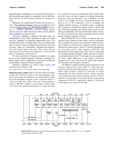
Radar frequency bands. Figure F38 shows that most radars
fundamental and environmental factors, without providing
occupy the microwave region of the electromagnetic spec-
exact tuning limits that might be militarily sensitive. The fre-
trum, but the range of frequencies over which different radars
quencies corresponding to each band, and the corresponding
have been designed to operate covers a spectrum nearly 17
assignments by the ITU, applicable to Region 2 (North and
octaves in width: from 2 MHz in the case of HF groundwave
South America), are shown in the table.
radars to 300 GHz or higher for laser radars. In theory, there
is no limit to the operational frequency of a radar, but there
Figure F38 Radar portion of the electromagnetic spectrum (from Skolnik, 1980, Fig. 1.4, p. 7, reprinted
by permission of McGraw-Hill).