
Page 206 - Radar Technology Encyclopedia
P. 206
filter, temporal [time] filter, Wiener 196
assigned coverage volume is monitored sequentially by beam
scanning. As a result, the observed image is a function of x(t) Delay Delay Delay Delay
1 2 3 m
time. IAM
Ref.: Baklitskiy (1986), p. 12.
w 1 w 2 w 3 w 4 w m w m+1
A tracking (loop) filter is a closed nonlinear filter designed
for evaluation of a parameter nonlinearly coded in a signal. A
y(t)
tracking loop filter nonlinear with respect to input signal +
t
S(L()) is similar to a linear filter with respect to its parameter
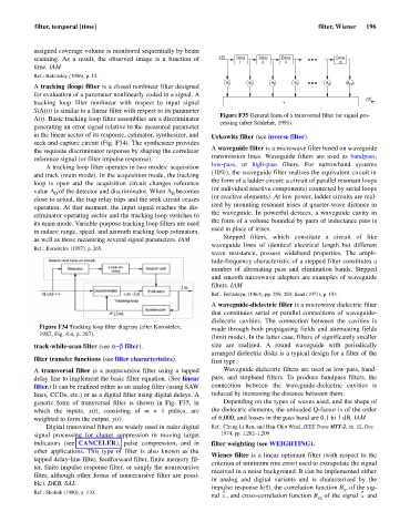
Figure F35 General form of a transversal filter for signal pro-
L(t). Basic tracking loop filter assemblies are a discriminator
cessing (after Schleher, 1991).
generating an error signal relative to the measured parameter
in the linear sector of its response, estimator, synthesizer, and Urkowitz filter (see inverse filter).
seek-and-capture circuit (Fig. F34). The synthesizer provides
A waveguide filter is a microwave filter based on waveguide
the requisite discriminator response by shaping the correlator
transmission lines. Waveguide filters are used as bandpass,
reference signal (or filter impulse response).
low-pass, or high-pass filters. For narrowband systems
A tracking loop filter operates in two modes: acquisition
(10%), the waveguide filter realizes the equivalent circuit in
and track (main mode). In the acquisition mode, the tracking
the form of a ladder circuit: a circuit of parallel resonant loops
loop is open and the acquisition circuit changes reference
(or individual reactive components) connected by serial loops
value L of the detector and discriminator. When L becomes
0
0
close to actual, the trap relay trips and the seek circuit ceases (or reactive elements). At low power, ladder circuits are real-
ized by mounting resonant irises at quarter-wave distance in
operation. At that moment, the input signal reaches the dis-
the waveguide. In powerful devices, a waveguide cavity in
criminator operating sector and the tracking loop switches to
the form of a volume bounded by pairs of inductance pins is
its main mode. Variable-purpose tracking loop filters are used
used in place of irises.
in radars: range, speed, and azimuth tracking loop estimators,
Stepped filters, which constitute a circuit of like
as well as those measuring several signal parameters. IAM
waveguide lines of identical electrical length but different
Ref.: Korostelev (1987), p. 265.
wave resistance, possess wideband properties. The ampli-
tude-frequency characteristic of a stepped filter constitutes a
number of alternating pass and elimination bands. Stepped
and smooth microwave adapters are examples of waveguide
filters. IAM
Ref.: Fel'dsteyn, (1963), pp. 259, 289; Saad (1971), p. 153.
A waveguide-dielectric filter is a microwave dielectric filter
that constitutes serial or parallel connections of waveguide-
dielectric cavities. The connection between the cavities is
Figure F34 Tracking loop filter diagram (after Korostelev,
made through both propagating fields and attenuating fields
1987, Fig. 8.4, p. 267).
(limit mode). In the latter case, filters of significantly smaller
track-while-scan filter (see a-b filter). size are realized. A round waveguide with periodically
arranged dielectric disks is a typical design for a filter of the
filter transfer functions (see filter characteristics). first type.
A transversal filter is a nonrecursive filter using a tapped Waveguide-dielectric filters are used as low-pass, band-
delay line to implement the basic filter equation. (See linear pass, and stopband filters. To produce bandpass filters, the
filter.) It can be realized either as an analog filter (using SAW connection between the waveguide-dielectric cavities is
lines, CCDs, etc.) or as a digital filter using digital delays. A reduced by increasing the distance between them.
generic form of transversal filter is shown in Fig. F35, in Depending on the types of waves used, and the shape of
which the inputs, x(t), consisting of m + 1 pulses, are the dielectric elements, the unloaded Q-factor is of the order
weighted to form the output, y(t). of 6,000, and losses in the pass band are 0.1 to 1 dB. IAM
Digital transversal filters are widely used in radar digital Ref.: Chung-Li Ren, and Han-Chiu Wand, IEEE Trans MTT-2, no. 12, Dec.
signal processing for clutter suppression in moving target 1974, pp. 1,202–1,209.
indicators (see CANCELER), pulse compression, and in filter weighting (see WEIGHTING).
other applications. This type of filter is also known as the
Wiener filter is a linear optimum filter (with respect to the
tapped delay-line filter, feedforward filter, finite memory fil-
criterion of minimum rms error) used to extrapolate the signal
ter, finite impulse response filter, or simply the nonrecursive
received in a noise background. It can be implemented either
filter, although other forms of nonrecursive filter are possi-
in analog and digital variants and is characterized by the
ble). DKB, SAL
impulse response h(t), the correlation function B , of the sig-
x
Ref.: Skolnik (1980), p. 110.
nal , and cross-correlation function B of the signal and
x
x
sx