
Page 201 - Radar Technology Encyclopedia
P. 201
191 filter, linear filter, microwave
For discrete filters this takes the form the mainlobe clutter exceeds the dynamic range of the A/D
¥ converter or digital filtering circuits. DKB
×
[
(
×
(
yn Dt ) = å xn – m ) D t ]hm Dt )× ( × Ref.: Schleher (1991), p. 66; Morris (1988), pp. 101–107.
m = – ¥ A matched filter is the optimum filter for a given signal in a
where Dt is the sampling interval. This expression can be rep- background of white noise, and as such it maximizes the out-
resented in the form that is the basic discrete filter equation: put ratio of peak signal power to mean noise power. It has a
frequency response H(f) that is the complex conjugate of the
M 1– N 1–
received spectrum A(f), or equivalently, has an impulse
(
×
(
×
[
(
[
×
yn Dt ) –= å b × yn – j ) D t ] + å a × xn – k ) D t ] response h(t) that is the time inverse of the received wave-
j
k
j = 1 k = 1 form s(t):
where a and b are filter weighting coefficients. If the coeffi- Hf () A * f ()
k
j
=
cients a ³ 0, b ³ 0, the filter is called a recursive filter, while
k
k
if all coefficients b = 0, it is a nonrecursive filter. The latter ht () ks t –= ( d t )
j
type is more widely used in radar digital signal processing. In where t is the time delay required to make the filter realiz-
d
this case, assuming h(0) = a , h(Dt) = a , ... , h(nDt)= a , this able, and k is a dimensional normalizing factor. These rela-
1
0
n
expression results in a formula basic to describing the nonre- tions lead to waveform-response pairs illustrated in Fig. F33.
cursive digital filter: When this filter is used, the ratio of output peak signal
n power to mean noise power is 2E/N , where E is the received
0
×
(
×
(
[
yn Dt ) = å a × xn – k ) D t ] signal energy and N is the noise spectral density referred to
0
k
the receiver input point at which E is measured. DKB
k = 0
where a are weighting coefficients. Strictly speaking, digital Ref.: Cook (1967), pp. 5–9; DiFranco (1968), pp. 143–184.
k
filtering is a nonlinear operation, but thanks to their simplic-
Amplitude
ity, linear filters are used not only for linear, but also for qua-
sioptimum, nonlinear filtering of radar signals. SAL, IAM
Frequency Frequency
Ref.: Gol’denberg (1985), p. 46.
Phase
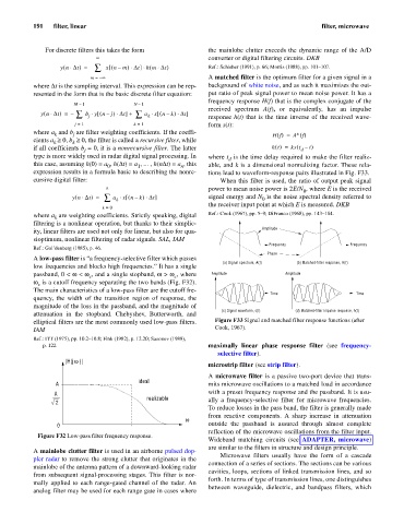
A low-pass filter is “a frequency-selective filter which passes
(a) Signal spectrum, A(f) (b) Matched-filter response, H(f)
low frequencies and blocks high frequencies.” It has a single
passband, 0 < w < w , and a single stopband, w > w , where Amplitude Amplitude
c
c
w is a cutoff frequency separating the two bands (Fig. F32).
c
The main characteristics of a low-pass filter are the cutoff fre-
Time Time
quency, the width of the transition region of response, the
magnitude of the loss in the passband, and the magnitude of
(c) Signal waveform, s(t) (d) Matched-filter impulse response, h(t)
attenuation in the stopband. Chebyshev, Butterworth, and
elliptical filters are the most commonly used low-pass filters. Figure F33 Signal and matched filter response functions (after
IAM Cook, 1967).
Ref.: ITT (1975), pp. 10.2–10.8; Fink (1982), p. 12.20; Sazonov (1988),
p. 122. maximally linear phase response filter (see frequency-
selective filter).
w
|H(j )|
microstrip filter (see strip filter).
A microwave filter is a passive two-port device that trans-
ideal
A mits microwave oscillations to a matched load in accordance
A with a preset frequency response and the passband. It is usu-
realizable ally a frequency-selective filter for microwave frequencies.
2
To reduce losses in the pass band, the filter is generally made
from reactive components. A sharp increase in attenuation
w
0 outside the passband is assured through almost complete
reflection of the microwave oscillations from the filter input.
Figure F32 Low-pass filter frequency response.
Wideband matching circuits (see ADAPTER, microwave)
are similar to the filters in structure and design principle.
A mainlobe clutter filter is used in an airborne pulsed dop-
Microwave filters usually have the form of a cascade
pler radar to remove the strong clutter that originates in the
connection of a series of sections. The sections can be various
mainlobe of the antenna pattern of a downward-looking radar
cavities, loops, sections of linked transmission lines, and so
from subsequent signal-processing stages. This filter is nor-
forth. In terms of type of transmission lines, one distinguishes
mally applied to each range-gated channel of the radar. An
between waveguide, dielectric, and bandpass filters, which
analog filter may be used for each range gate in cases where