
Page 198 - Radar Technology Encyclopedia
P. 198
filter, frequency-selective filter, high-pass 188
finite-impulse-response (FIR) filter (see recursive filter).
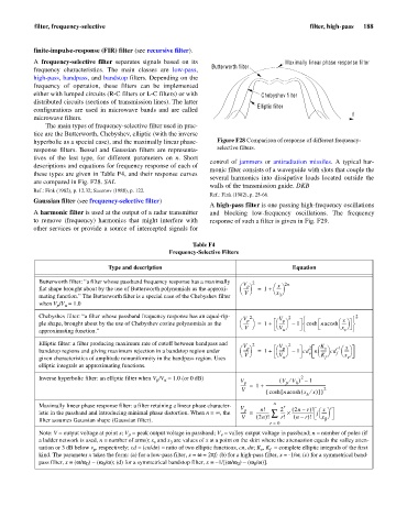
A frequency-selective filter separates signals based on its Maximally linear phase response filter
Butterworth filter
frequency characteristics. The main classes are low-pass,
high-pass, bandpass, and bandstop filters. Depending on the
frequency of operation, these filters can be implemented
either with lumped circuits (R-C filters or L-C filters) or with Chebyshev filter
distributed circuits (sections of transmission lines). The latter
Elliptic filter
configurations are used in microwave bands and are called
f
microwave filters.
The main types of frequency-selective filter used in prac-
tice are the Butterworth, Chebyshev, elliptic (with the inverse
hyperbolic as a special case), and the maximally linear phase- Figure F28 Comparison of response of different frequency-
response filters. Bessel and Gaussian filters are representa- selective filters.
tives of the last type, for different parameters on n. Short
control of jammers or antiradiation missiles. A typical har-
descriptions and equations for frequency response of each of
monic filter consists of a waveguide with slots that couple the
these types are given in Table F4, and their response curves
several harmonics into dissipative loads located outside the
are compared in Fig. F28. SAL
walls of the transmission guide. DKB
Ref.: Fink (1982), p. 12.32; Sazonov (1988), p. 122.
Ref.: Fink (1982), p. 25-66.
Gaussian filter (see frequency-selective filter)
A high-pass filter is one passing high-frequency oscillations
A harmonic filter is used at the output of a radar transmitter and blocking low-frequency oscillations. The frequency
to remove (frequency) harmonics that might interfere with response of such a filter is given in Fig. F29.
other services or provide a source of intercepted signals for
Table F4
Frequency-Selective Filters
Type and description Equation
Butterworth filter: “a filter whose passband frequency response has a maximally V 2 2n
x
-----
flat shape brought about by the use of Butterworth polynomials as the approxi- æ ------ p ö = 1 + æö
è V ø x èø
mating function.” The Butterworth filter is a special case of the Chebyshev filter 3
when V /V = 1.0
u
p
Chebyshev filter: “a filter whose passband frequency response has an equal-rip- V 2 V 2 ì ü
2
x
----
ple shape, brought about by the use of Chebyshev cosine polynomials as the æ ------ p ö = 1 + æ ------ p ö – 1 í cosh nacosh æö ý
è V ø è V ø x èø
approximating function.” u î v þ
Elliptic filter: a filter producing maximum rate of cutoff between bandpass and V 2 V 2 K
2
v ö – æö
æ
----
bandstop regions and giving maximum rejection in a bandstop region under æ ------ p ö = 1 + æ ------ p ö – 1 cd n ------ cd 1 x
è V ø è V ø v è K ø f èø
x
given characteristics of amplitude nonuniformity in the bandpass region. Uses u f v
elliptic integrals as approximating functions.
Inverse hyperbolic filter: an elliptic filter when V /V = 1.0 (or 0 dB) V ( V ¤ V ) 1–
2
p
u
p
h
p
------ = 1 + ------------------------------------------------------------
V { cosh [ ( 2
x ¤ )]}
nacosh
h x
n
Maximally linear phase response filter: a filter retaining a linear phase character- r
V p n! 2 ( 2n – r ) ! æ x ö
r
istic in the passband and introducing minimal phase distortion. When n = ¥ , the ------ = ------------- å ----- ´ --------------------- j -----
V ( 2n ) ! r! ( n – r ) ! x è ø
filter assumes Gaussian shape (Gaussian filter). b
r = 0
Note: V = output voltage at point x; V = peak output voltage in passband; V = valley output voltage in passband; n = number of poles (if
v
p
a ladder network is used, n = number of arms); x and x are values of x at a point on the skirt where the attenuation equals the valley atten-
v
3
uation or 3 dB below v , respectively; cd = (cn/dn) = ratio of two elliptic functions, cn, dn; K , K = complete elliptic integrals of the first
p
f
v
kind. The parameter x takes the form: (a) for a low-pass filter, x = w = 2p f; (b) for a high-pass filter, x = -1/w; (c) for a symmetrical band-
pass filter, x = (w/w ) - (w /w); (d) for a symmetrical bandstop filter, x = - 1/[(w/w ) - (w /w)].
0
0
0
0