
Page 197 - Radar Technology Encyclopedia
P. 197
187 filter, digital filter, ferrite
tages over analog filters are in stability and repeatability of
T T
response, flexibility and reliability of operation, and conve- H = [ h ¼ h , á [ yn () yn – 1 )¼ yn () yn – N )]ñ
] P =
(
(
1 N
nience of implementation using integrated circuit technology. Filter coefficients h are selected from the condition of mini-
k
SAL mizing of the mean-square prediction error:
Ref.: Jordan (1985), pp. 28.7–28.18.
2 ˆ 2
=
–
A directional filter is a frequency-selective directional cou- á e n ()ñ á [ yn () y n ()]ñ
pler. The frequency characteristic of the directional filter in and are found through solution of Wiener equa-
–
1
the circuit between branches corresponds to the frequency tion H = R P , where
opt
characteristic of a bandstop filter.
A waveguide directional filter with high Q-factor con- and
sists of a cylindrical three-dimensional cavity connected to
T
(
[
(
(
(
two rectangular waveguides through round openings. Typical R = á [ y n – 1 )¼ yn – N )] yn – 1 )¼ yn – N )]ñ
bandwidths are 0.2 to 0.4%, losses less than 0.3 dB, tuning
is the input signal autocorrelation matrix. Figure F27 shows a
within the limits of 10% of the band (in X-band). It is used in
diagram of the filter in z-transform terms.
radars, in circuits feeding a mixer from a low-power oscilla-
Evaluation of the signal at the (n - N)th moment, based
tor, and also for suppression of interference at frequencies
on preceding observations, is used along with prediction of
close to the carrier frequency of the radar.
the signal extrapolated in time. These evaluations are
Directional filters based on yttrium-iron-garnet (YIG) fil-
obtained simultaneously in a lattice filter. A filter-extrapola-
ters are marked by a broad adjustment and electronic tuning.
tor is used in signal coding, noise suppression, and data
Losses of such filters is 2.5 dB, minimum decoupling in the
smoothing. (See Kalman filter.) IAM
region outside the resonance band of 45 dB and maximum
Ref.: Gol’denberg (1985), p. 167; Blackman (1986).
coupling coefficient on the order of 1.5 within the range of 8
to 12.4 GHz. IAM
y(n)
Ref.: Skolnik (1970), p. 8.29.
z -1 z -1 z -1
A discrete filter is one processing discrete signals (sampled
in the time domain). In radar applications a CCD filter is
h h 2 h
often used. The theory of discrete filter operation is described 1 N
by the discrete filtering equation (see linear filter) and is the
basis for the theory and implementation of digital filters. SAL
Ref.: Karteshev (1982), p. 11; Fink (1982),p. 12.44. S e (n)
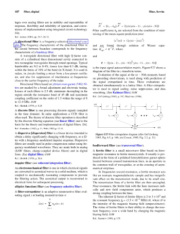
A dispersive [dispersion] filter is a linear device intended to
Figure F27 Filter-extrapolator diagram (after Gol’denberg,
obtain a delay significantly changing with frequency, or a fil- 1985, Fig. 6.5, p. 169, and Cowan, 1985, Fig. 2.2, p. 32).
ter with a frequency-modulated impulse response. Dispersive
filters are usually used in pulse-compression radars using fre-
feedforward filter (see transversal filter).
quency-modulated waveforms. They are made both in analog
(SAW filters, charge-coupled device filters) and in digital A ferrite filter is a small microwave filter based on ferro-
form. (See digital filter.) IAM magnetic resonance in ferrite monocrystals. It usually is pro-
Ref.: Skolnik (1970), p. 20.6. duced in the form of a polished ferroyttriferous garnet sphere
located between crossed transmission lines, in an aperture in
doppler filter (see coherent integration filter).
the common wall of waveguides, or at the crossing of asym-
An electromechanical filter is one in which electrical signals metrical striplines.
are converted to acoustical waves in a solid medium, which is At frequencies toward resonance, a ferrite resonator acts
coupled to mechanically resonating components to provide like an isotropic magnetodielectric sample and has insignifi-
the filtering action. The acoustical output is reconverted to cant effect on the transmission mode, due to its small size.
electrical form for subsequent processing. The transmission lines of a ferrite filter are then uncoupled.
elliptic(-function) filter (see frequency-selective filter). Near resonance, the ferrite link with the lines increases radi-
cally and new field components arise, which produces a
A filter-extrapolator is an adaptive nonrecursive filter eval-
strong coupling between the lines.
uating signal y at leading moment in time n: 3
The inherent Q-factor of ferrite filters is 2 to 3 ´ 10 and
N - 2
the resonant frequency f » (3.5 ´ 10 MHz)×H, where H is
0
ˆ
(
y n () = å h yn – k ) the intensity of the magnetic biasing field (amperes/meter).
k
The virtue of ferrite filters is their ability to change the reso-
k = 1
nant frequency over a wide band by changing the magnetic
biasing field. IAM
Ref.: Sazonov (1988), p. 178.