
Page 192 - Radar Technology Encyclopedia
P. 192
field strength, magnetic filter, acousto-optical 182
The magnetic field strength measures the magnetic effects IIR) or nonrecursive (finite impulse response, FIR, or trans-
caused by a flowing electrical current. It is a field vector H versal) filters. The latter type is most widely used.
measuring the amount of force F produced per unit of mag- (3) This type of filter is an algorithm processing a set of
netic flux set up by a conductor consisting of N closely individual estimates (e.g., radar measurements obtained over
spaced turns each carrying the same current I through a con- successive time periods) with the objective of obtaining a
ductor of closed-path length l, in a medium of permeability m. new estimate for time t . If t is equal to or less than the cur-
n
n
Magnetic field strength can be expressed by the vector equa- rent time t when the last measurement is made, the operation
j
tion is termed smoothing (or interpolation); if t > t , it is termed
j
n
prediction or extrapolation. The two basic types of filter per-
B
H = ----- forming these operations are the a-b(-g) filter and the Kalman
m
filter.
where B is the magnetic flux density. The magnetic field
In Russian literature the operations performed by the fil-
strength is measured in ampere-turns/meter. PCH
ters described in (2) are termed “primary signal processing,”
Ref.: Fink (1982), p. 1-22.
and those in (3) are “secondary signal processing”. SAL
FILTER, FILTERING. In radar applications the terms filter An a-b(-g) is a recursive filter used in track-while-
r
e
t
l
fi
and filtering are used in the following three senses: scan radar and other sampled-data systems to smooth and
(1) One type of filter is a frequency-selective circuit that extrapolate past data. At the time of the nth data point in a
separates the radar signal from its background based on the sequence, an estimate of the smoothed position x in coordi-
ns
signal frequency spectrum. Filters of this type are referred to nate x is made using
as frequency(-selective) filters, classified as low-pass, high-
x = x + a x – x )
(
pass, bandpass, or band-stop filters. Depending on the center ns pn n pn
frequency, tuned filters are divided into radio-frequency (RF, where x is the value predicted from past data, x is the mea-
n
pn
or microwave) filters, intermediate-frequency (IF) filters, or sured value for the nth point, and a is the position smoothing
video filters, and, depending on bandwidth, into narrowband parameter. At the same time, an estimate of smoothed veloc-
·
or wideband filters. These are used primarily in the radar ity x ns is made, using
receiver. · · b
(
(2) A second type of filter is a two-port device providing x ns = x n 1– + --- x – x pn )
n
T
a required output based on its input signal. In this sense it is a where b is the velocity-smoothing parameter, and T is the data
major component of the radar signal processor. An optimum interval. It is apparent that a = b 0 rejects new data, produc-
=
filter (which is termed a matched filter for a background of ing a track that follows previous predictions, while a = b = 1
white noise) gives the highest signal-to-noise ratio at its out- rejects past data, producing a track following each new point
put, for given input signal energy. Signal processing filters are as it is measured.
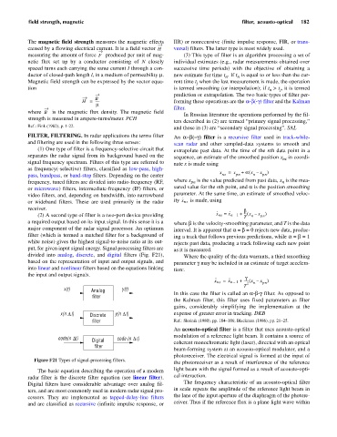
divided into analog, discrete, and digital filters (Fig. F21), Where the quality of the data warrants, a third smoothing
based on the representation of input and output signals, and parameter g may be included in an estimate of target accelera-
into linear and nonlinear filters based on the equations linking tion:.
the input and output signals.
·· ·· g
x ns = x n – + ----- x – x pn )
(
1
n
2
T
x(t) Analog y(t)
filter In this case the filter is called an a-b-gfilter. As opposed to
the Kalman filter, this filter uses fixed parameters as filter
gains, considerably simplifying the implementation at the
x(n t) Discrete y(n t) expense of greater error in tracking. DKB
D
D
filter Ref.: Skolnik (1980), pp. 184–186; Blackman (1986), pp. 21–25.
An acousto-optical filter is a filter that uses acousto-optical
modulation of a reference light beam. It contains a source of
code(n t) Digital code (n t)
D
D
filter coherent monochromatic light (laser), directed with an optical
beam-forming system at an acousto-optical modulator, and a
photoreceiver. The electrical signal is formed at the input of
Figure F21 Types of signal-processing filters.
the photoreceiver as a result of interference of the reference
The basic equation describing the operation of a modern light beam with the signal formed as a result of acousto-opti-
radar filter is the discrete filter equation (see linear filter). cal interaction.
Digital filters have considerable advantage over analog fil- The frequency characteristic of an acousto-optical filter
ters, and are most commonly used in modern radar signal pro- in scale repeats the amplitude of the reference light beam in
cessors. They are implemented as tapped-delay-line filters the lane of the input aperture of the diaphragm of the photore-
and are classified as recursive (infinite impulse response, or ceiver. Thus if the reference flux is a plane light wave within