
Page 194 - Radar Technology Encyclopedia
P. 194
filter, bandpass filter characteristics 184
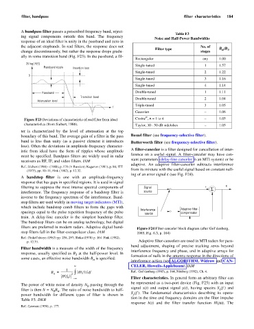
A bandpass filter passes a prescribed frequency band, reject-
Table F3
ing signal components outside this band. The frequency
Noise and Half-Power Bandwidths
response of an ideal filter is unity in the passband and zero in
the adjacent stopbands. In real filters, the response does not No. of
Filter type B /B 3
n
change discontinuously, but rather the response drops gradu- stages
ally in some transition band (Fig. F23). In the passband, a fil-
Rectangular any 1.00
20 log |H(f)| Single-tuned 1 1.57
Passband ripple Insertion loss
Single-tuned 2 1.22
0
Single-tuned 3 1.16
Single-tuned 4 1.14
Passband Double-tuned 1 1.11
Transition band Double-tuned 2 1.04
Attenuation level
Triple-tuned 3 1.05
f
Gaussian – 1.06
n
Figure F23 Deviations of characteristic of real filter from ideal Cosine , n = 1 to 4 – 1.05
characteristics (from Siebert, 1986). Taylor, 30 - 50 dB sidelobes – 1.05
ter is characterized by the level of attenuation at the top
boundary of this band. The average gain of a filter in the pass Bessel filter (see frequency-selective filter).
band is less than unity (as a passive element it introduces Butterworth filter (see frequency-selective filter).
loss). Often the deviations in amplitude-frequency character-
A filter-canceler is a filter designed for cancellation of inter-
istic from ideal have the form of ripples whose amplitude
ference on a useful signal. A filter-canceler may have con-
must be specified. Bandpass filters are widely used in radar
stant parameters (delay-line canceler in an MTI system) or be
receivers as RF, IF, and video filters. IAM
adaptive. An adaptive filter-canceler subtracts interference
Ref.: Siebert (1986)– (1988), p. 176 (in Russian); Kaganov (1981), p. 86; ITT
(1975), pp. 10–11; Fink (1982), p. 12.32. from its mixture with the useful signal based on constant null-
ing of an error signal e (see Fig. F24).
A bandstop filter is one with an amplitude-frequency
response that has gaps in specified regions. It is used in signal
filtering to suppress the most intense spectral components of Signal + S e
interference. The frequency response of a bandstop filter is source
inverse to the frequency spectrum of the interference. Band-
stop filters are used widely in moving target indicators (MTI),
which include bandstop comb filters to form the gaps with
Interference Adaptive filter-
spacings equal to the pulse repetition frequency of the pulse source compensator
train. A delay-line canceler is the simplest bandstop filter.
The bandstop filters can be on analog technology, but digital
filters are preferred in modern radars. Adaptive digital band- Figure F24 Filter-canceler block diagram (after Gol’denberg,
stop filters fall in the filter-extrapolator class. IAM 1985, Fig. 6.3, p. 164)
Ref.: Finkel’shteyn (1983) pp. 258, 297; Sloka (1970) p. 164. Fink (1982),
p. 12.33. Adaptive filter-cancelers are used in MTI radars for pass-
band adjustment, shaping of precise tracking zeros beyond
Filter bandwidth is a measure of the width of the frequency
interference frequency and phase, and in adaptive arrays for
response, usually specified as B at the half-power level. In formation of nulls in the antenna response in the directions of
3
some cases, an effective noise bandwidth B is specified:
n
interference action (see ALGORITHM, Widrow and CAN-
¥ CELER, Howells-Applebaum). IAM
1
B = ------------------- Hf )()f Ref.: Gol’denberg (1985), p. 164; Nitzberg (1992), Ch. 4.
d
n 2 ò
Hf ()
0
– ¥ Filter characteristics. In general form an arbitrary filter can
be represented as a two-port device (Fig. F25) with an input
The power of white noise of density N passing through the
0
x
filter is then N = N B . The ratio of noise bandwidth to half- signal x(t) and output signal y(t), having spectra S (f ) and
0 n
y
power bandwidth for different types of filter is shown in S (f ). The fundamental characteristics describing its opera-
tion in the time and frequency domains are the filter impulse
Table F3. DKB
response h(t) and the filter transfer function H(jw). The
Ref.: Lawson (1950), p. 177.