
Page 191 - Radar Technology Encyclopedia
P. 191
181 FENCE field strength [intensity], electromagnetic
press ground clutter” (the latter is more often termed a clutter In the far field, the electrical field strength is given by
fence). – jkR 0
e jwt
,,
Ref.: IEEE (1990), p. 16; Skolnik (1970), p. 32.8. E fqR ) I × -------------- f fq,( )e ×
(
×
=
0 0 R
A clutter fence is a “concentric conducting barrier erected 0
where fq, R are the spherical coordinates of point P with
,
around a ground-based radar to serve as an artificial horizon 0
respect to the center of the antenna and I is the complex
and suppress ground clutter.” The main task of such a fence is 0
amplitude of the current a radiating element at point O
to reduce the reflections from large clutter sources; for exam-
(Fig. 20). This equation shows the structure of the antenna
ple, nearby mountains, which cannot be eliminated by radar
field, which consists of four multiplicative factors:
clutter-suppression techniques such as MTI. Such a fence typ-
(1) I describes the intensity of a field at the antenna
ically is made from an electromagnetically opaque material 0
aperture.
preventing the radar from viewing the clutter directly but also – jkR 0
(2) e ¤ R , where k = 2p/l is the wave number,
limiting the ability of the radar to detect low-altitude targets. 0
describes the dependence of the field on the distance from the
The typical two-way isolation provided by such a fence is
antenna.
about 40 dB. SAL
(3) f(f,q) describes the dependence on the angular coor-
Ref.: IEEE (1990), p. 16; Barton (1975), p. 363; Skolnik (1980), p. 497.
dinates (spatial distribution) and is virtually the antenna pat-
FERRITE. A ferrite is a ceramic material prepared from a tern.
mixture of powdered iron oxide and oxides of other metals (4) e jwt , where w is the angular frequency of the radiated
such as copper or nickel. The powder is mixed with a binder wave, describes the temporal structure of the field (see also
and annealed, resulting in a hard material. Ferrites are charac- ANTENNA radiation regions). SAL
terized by their permeability and loss. The main types of fer- Ref.: Johnson (1984), p. 1.9; Fradin (1977), p. 19.
rites are spinel, magnetoplambite, and garnet. They are
widely used in RF components for radar, especially in circu- z
lators and phase shifters. There main limitations are fragility, P
difficulties in mechanical processing because of hardness,
temperature dependence, and aging. SAL R 0
Ref.: Fink (1982), pp. 6.77, 9.20; Zherebtsov (1989), p. 170.
FIELD, electromagnetic. The electromagnetic field consists I 0
q
of electric and magnetic fields completely described by four O y
vectors:
E = electric field strength (intensity).
D = electric field induction. f
H = magnetic field strength (intensity). x
B = magnetic field induction.
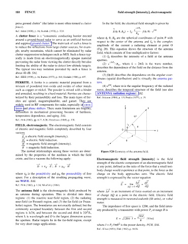
The mutual relationships among these vectors are deter- Figure F20 Geometry of the antenna field.
mined by the properties of the medium in which the field
exists, and for a vacuum the following apply: Electromagnetic field strength [intensity] is the field
strength of the electric component of an electromagnetic field
×
D = e E B ; = m × H at any point, defined as the ratio of the force that a small test-
0 0
body charge would experience at that point, to the force as the
where e is the permittivity and m the permeability of free charge on the body approaches zero. The electric field
0
0
space. For a description of the resulting propagating wave, strength is expressed by the vector equation
see WAVE. SAL DF dF
Ref.: Fink (1982), p. 1.38; Nikol’skiy (1964). E = lim --------- = --------
DQ ® 0 dQ dQ
The antenna field is the electromagnetic field produced by where DF is an increment of force exerted on an increment
an antenna during operation. This is divided into three of charge DQ at a point in the electric field. Electric field
regions: (1) the reactive near-field region, (2) the radiating strength is measured in newtons/coulomb (SI units), or volts/
near-field (or Fresnel) region, and (3) the far-field (or Fraun- meter.
hofer) region. The boundaries are not exactly defined, but the The impedance of free space is 120p, d the field inten-
an
commonly accepted boundary between the first and second sity produced by a transmitter with power P at range R is
t
2
regions is l/2p, and between the second and third is 2D /l,
where l is wavelength and D is the largest dimension across 30P t
E = 120p I × = --------------- [V/m]
the aperture. Radar targets lie in the far-field region, except R
for very short-range applications. where I = P /4pR is the power density. PCH, SAL
2
t
Ref.: Silver (1951); Fink (1982), p. 18.56.