
Page 113 - Rapid Learning in Robotics
P. 113
7.2 Sensor Fusion and 3 D Object Pose Identification 99
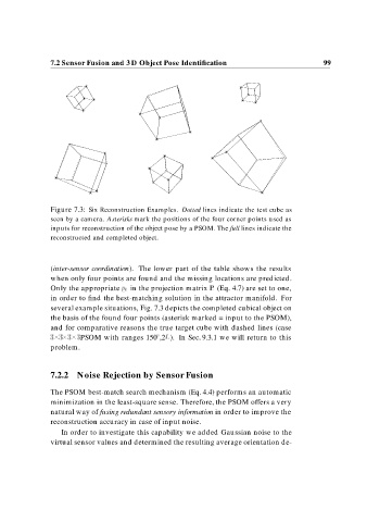
Figure 7.3: Six Reconstruction Examples. Dotted lines indicate the test cube as
seen by a camera. Asterisks mark the positions of the four corner points used as
inputs for reconstruction of the object pose by a PSOM. The full lines indicate the
reconstructed and completed object.
(inter-sensor coordination). The lower part of the table shows the results
when only four points are found and the missing locations are predicted.
Only the appropriate p k in the projection matrix P (Eq. 4.7) are set to one,
in order to find the best-matching solution in the attractor manifold. For
several example situations, Fig. 7.3 depicts the completed cubical object on
the basis of the found four points (asterisk marked = input to the PSOM),
and for comparative reasons the true target cube with dashed lines (case
PSOM with ranges 150 ,2L). In Sec. 9.3.1 we will return to this
problem.
7.2.2 Noise Rejection by Sensor Fusion
The PSOM best-match search mechanism (Eq. 4.4) performs an automatic
minimization in the least-square sense. Therefore, the PSOM offers a very
natural way of fusing redundant sensory information in order to improve the
reconstruction accuracy in case of input noise.
In order to investigate this capability we added Gaussian noise to the
virtual sensor values and determined the resulting average orientation de-