
Page 283 - Reciprocating Compressors Operation Maintenance
P. 283
268 Reciprocating Compressors: Operation and Maintenance
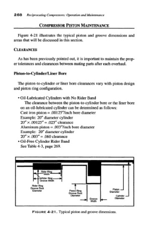
Figure 4-21 illustrates the typical piston and groove dimensions and
areas that will be discussed in this section.
CLEARANCES
As has been previously pointed out, it is important to maintain the prop-
er tolerances and clearances between mating parts after each overhaul.
Piston-to-Cylinder/Liner Bore
The piston-to-cylinder or liner bore clearances vary with piston design
and piston ring configuration.
• Oil-Lubricated Cylinders with No Rider Band
The clearance between the piston-to-cylinder bore or the liner bore
on an oil-lubricated cylinder can be determined as follows:
Cast iron piston = .00125'Vinch bore diameter
Example: 20" diameter cylinder
20" x .00125" = .025" clearance
Aluminum piston = .003"/inch bore diameter
Example: 20" diameter cylinder
20" x .003" = .060 clearance
«Oil-Free Cylinder Rider Band
See Table 4-3, page 269.
FIGURE 4-21. Typical piston and groove dimensions.