
Page 42 - Reciprocating Compressors Operation Maintenance
P. 42
Reciprocating Compressors and Their Applications 29
Discharge Volume of Compressed Air
yalve Suction Valve Compressed to
100 psi Discharged at t
100 psi
~^ P i P i > [z^pSB
r
WWrnrTl T
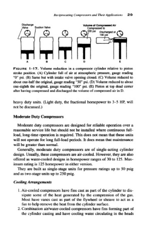
FIGURE 1-17. Volume reduction in a compressor cylinder relative to piston
stroke position. (A) Cylinder full of air at atmospheric pressure, gauge reading
"0" psi, (B) Same but with intake valve opening closed. (C) Volume reduced to
about one-half the original, gauge reading "50" psi. (D) Volume reduced to about
one-eighth the original, gauge reading "100" psi. (E) Piston at top dead center
after having compressed and discharged the volume of compressed air in D.
heavy duty units. (Light duty, the fractional horsepower to 3-5 HP, will
not be discussed.)
Moderate Duty Compressors
Moderate duty compressors are designed for reliable operation over a
reasonable service life but should not be installed where continuous full-
load, long-time operation is required. This does not mean that these units
will not operate for long full-load periods. It does mean that maintenance
will be greater than normal.
Generally, moderate duty compressors are of single-acting cylinder
design. Usually, these compressors are air-cooled. However, they are also
offered as water-cooled designs in horsepower ranges of 30 to 125. Max-
imum rating is 125 horsepower in either version.
They are built as single-stage units for pressure ratings up to 50 psig
and as two-stage units up to 250 psig.
Cooling Arrangements
1. Air-cooled compressors have fins cast as part of the cylinder to dis-
sipate some of the heat generated by the compression of the gas.
Most have vanes cast as part of the flywheel or sheave to act as a
fan to help remove the heat from the cylinder surface.
2. Combination air/water-cooled compressors have fins forming part of
the cylinder casting and have cooling water circulating in the heads