
Page 46 - Reciprocating Compressors Operation Maintenance
P. 46
°;:^ 3 r— • - I T __ _ 3
\ NEAD END \ /'CRANK ENO /
Idealized PV Diagram £ \ OlAGflA» X / DIAGRAM /
(Indicator Card) |>
\ >V / /
|AJ s\ ^k.
re \
\
Ck. X. /
'
1 's' \ /v^»
SUCTION
PRESSURE 4 4'
1
S
•«M»» STROKE/VOLUME
HEAD CRANK
END END
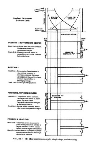
POSITION 1. BOTTOM DEAD CENTER I /A
sf
Head End— Cylinder filled at suction pressure. J
Intake valve closes and J
compression begins. j jj"*
Crank End— Clearance volume begins to JL CRANK ENO 3T
^*
expand to drop cylinder pressure I D CLEARANCE "C" — -* ^
f
below discharge. T
POSITION 2
Head End — Compression has advanced to s $f
raise cylinder pressure to I
discharge pressure. Discharge
valve opens and gas at discharge
pressure is pushed out to 0
discharge passage.
Crank End— Suction gas filling cylinder.
POSITION 3. TOP DEAD CENTER p i
CLEARANCE "C" 1
Head End — Compression stroke complete. \{ <* HEAD ENO Sj
Discharge valve closes as piston iL S* i
leaves top dead center. I/
T^
Clearance volume filled with gas ]// " " |""' J
at discharge pressure. pv
I
Crank End— Suction stroke complete. Intake t/ C J
valve closes; compression begins. T>
I
POSITION 4. HEAD END j I
Head End— Clearance volume expanded to ] s
point where pressure in cylinder is r '
slightly less than suction. Gas at I J
intake pressure begins to fill cylinder. 1 S^
Crank End — Compression in progress. Cylinder r 0
pressure above suction but not yet V J
at discharge pressure. [ ]
FIGURE 1-18. Ideal compression cycle, single-stage, double-acting.