
Page 420 - Reciprocating Compressors Operation Maintenance
P. 420
Reciprocating Compressor Calculations 4O5
*e v = 100 - L - %C1 • (A-16)
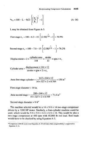
L may be obtained from Figure A-3.
26
First stage £ v = 100 - 6.3 -15 (2.58) - = 76.9%
Second stage 6 V = 100 - 7.0 -15 (2.58) i.26 _ } = 76.2%
_. . „ cylinder area stroke
Displacement = 2 x — x x rpm x e.
144 12
_ ,. . displacement x 144 x 12
Cylinder area = —
stroke x rpm x 2 x e v
A f- > * r A 612x144x12 tcn . 2
Area first-stage cylinder = = 150 in
14 x 327 x 2 x 0.769
First-stage diameter = 14 in.
. . 288x144x12 _ t . . 2
Area second stage = = 71.4 in
14 x 327 x 2 x 0.769
Second-stage diameter = 9-%"
The machine selected would be a 14 x 9-% x 14 two-stage compressor
driven by a 1200 HP motor. Similarly, a four-cylinder machine could be
used, which would be 9-% x 9-% x 6-% x 6-% x 14. This would be also a
two-stage compressor at 400 rpm with 45,000 Ib rod load. Rod loads
would have to be checked by using Equation A-3,
""Comparison with the more exact Equation A-10 will show that compressibility is neglected in
Equation A-16.