Page 416 - Reciprocating Compressors Operation Maintenance
P. 416

Reciprocating  Compressor Calculations  401


           Suction temperature     60°F
           Suction pressure        150 psia
           Discharge pressure      1000 psia
           Flow        rate        9MMSCFD
           (Compression ratio      6.67  overall, or V6j67 = 2.58  per  stage

           From Figure A-1, we obtain a discharge  temperature of 308°F.

           Specific gravity of gas =  17.76/28.97 =0.613
                                         Z s = 0.98
                                         Z d = 0.97
                                       7    = 0.975
                                         avg.
           k-1    0 26
                   — - 0.206
             k    1.26
                                   10 6  P std  T s   1
           Capacity -9MMSCFDX          x     x     x —
                                   1440   P s  T stt,  Z s
                           6
                     „   10     14.4  520    1
                       vx
                              v/
                                    A
                                          A
                     J
                   —  O  A   A      vx    \r
                         1440   150   520   0.98
                   = 612ACFM
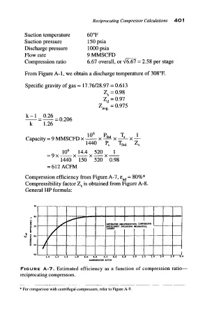
           Compression  efficiency from  Figure A-7, e ad = 80%*
           Compressibility  factor Z s is obtained from Figure A-8.
           General  HP formula:


             „  80
                                           EITIIUTID  KIClrROCATINO  COW>»»SSOR
                                          »ff«IIH«
                                                     MtCHANICM,
                                                IHCUIDJHa
             i        >                    LOStlS
           ^  ° 4  f /
                                                                        j
                   1
                                    COMFRIItlOH  RATIO
          "IGURE  A-7.  Estimated  efficiency  as  a  function  of  compression  ratio
          jciprocating compressors.


         * For comparison with centrifugal  compressors, refer to Figure A-9
   411   412   413   414   415   416   417   418   419   420   421