
Page 288 - Renewable Energy Devices and System with Simulations in MATLAB and ANSYS
P. 288
Marine and Hydrokinetic Power Generation and Power Plants 275
Induction Turbine Collector
generator transformer bus
G-box
Grid
PFC
capacitors
FIGURE 11.8 Type 1 MHK generator—induction generator. (Courtesy of NREL, Denver, CO.)
Induction Collector
generator bus
G-box
Turbine Grid
transformer
Variable
resistor
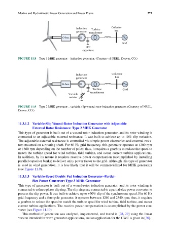
FIGURE 11.9 Type 2 MHK generator—variable-slip wound-rotor induction generator. (Courtesy of NREL,
Denver, CO.)
11.3.1.2 Variable-Slip Wound-Rotor Induction Generator with Adjustable
External Rotor Resistance: Type 2 MHK Generator
This type of generator is built out of a wound-rotor induction generator, and its rotor winding is
connected to an adjustable external resistance. It was built to achieve up to 10% slip variation.
The adjustable external resistance is controlled via simple power electronics and external resis-
tors mounted on a rotating shaft. For 60 Hz grid frequency, this generator operates at 1200 rpm
or 1800 rpm depending on the number of poles; thus, it requires a gearbox to reduce the speed to
match the turbine speed for wind turbine, tidal turbine, and ocean current turbine applications.
In addition, by its nature it requires reactive power compensation (accomplished by installing
parallel capacitor banks) to deliver unity power factor to the grid. Although this type of generator
is used in wind generation, it is less likely that it will be commercialized for MHK generation
(see Figure 11.9).
11.3.1.3 Variable-Speed Doubly Fed Induction Generator–Partial-
Size Power Converter: Type 3 MHK Generator
This type of generator is built out of a wound-rotor induction generator, and its rotor winding is
connected to a three-phase slip ring. The slip rings are connected to a partial-size power converter to
process the slip power. It was built to achieve up to +30% slip of the synchronous speed. For 60 Hz
grid frequency and a four-pole generator, it operates between 1260 and 2340 rpm; thus, it requires
a gearbox to reduce the speed to match the turbine speed for wind turbine, tidal turbine, and ocean
current turbine applications. The reactive power compensation is accomplished by the power con-
verter (see Figure 11.10).
This method of generation was analyzed, implemented, and tested in [28, 29] using the linear
version intended for wave generator applications, and an application for the OWC is given in [30].