
Page 289 - Renewable Energy Devices and System with Simulations in MATLAB and ANSYS
P. 289
276 Renewable Energy Devices and Systems with Simulations in MATLAB and ANSYS ®
®
Collector
Turbine
DFIG transformer bus
G-box
Grid
Power converter
Thyristors
Crowbar resistors
FIGURE 11.10 Type 3 MHK generator—variable-speed doubly fed induction generator. (Courtesy of NREL.)
Collector
PWM converter bus
PMSG Turbine Grid
transformer
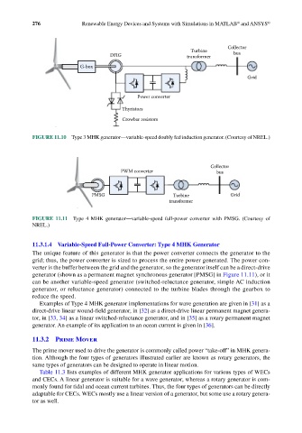
FIGURE 11.11 Type 4 MHK generator—variable-speed full-power converter with PMSG. (Courtesy of
NREL.)
11.3.1.4 Variable-Speed Full-Power Converter: Type 4 MHK Generator
The unique feature of this generator is that the power converter connects the generator to the
grid; thus, the power converter is sized to process the entire power generated. The power con-
verter is the buffer between the grid and the generator, so the generator itself can be a direct-drive
generator (shown as a permanent magnet synchronous generator [PMSG] in Figure 11.11), or it
can be another variable-speed generator (switched-reluctance generator, simple AC induction
generator, or reluctance generator) connected to the turbine blades through the gearbox to
reduce the speed.
Examples of Type 4 MHK generator implementations for wave generation are given in [31] as a
direct-drive linear wound-field generator, in [32] as a direct-drive linear permanent magnet genera-
tor, in [33, 34] as a linear switched-reluctance generator, and in [35] as a rotary permanent magnet
generator. An example of its application to an ocean current is given in [36].
11.3.2 Prime Mover
The prime mover used to drive the generator is commonly called power “take-off” in MHK genera-
tion. Although the four types of generators illustrated earlier are known as rotary generators, the
same types of generators can be designed to operate in linear motion.
Table 11.3 lists examples of different MHK generator applications for various types of WECs
and CECs. A linear generator is suitable for a wave generator, whereas a rotary generator is com-
monly found for tidal and ocean current turbines. Thus, the four types of generators can be directly
adaptable for CECs. WECs mostly use a linear version of a generator, but some use a rotary genera-
tor as well.