
Page 290 - Renewable Energy Devices and System with Simulations in MATLAB and ANSYS
P. 290
Marine and Hydrokinetic Power Generation and Power Plants 277
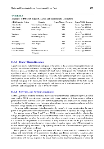
TABLE 11.3
Examples of Different Types of Marine and Hydrokinetic Generators
MHK Generator System Example Type of Energy Converter Type of MHK Generator
Point absorber Columbia Power Technologies WEC Rotary—Type 4 PMSG
Point absorber Ocean Power Technologies WEC Rotary—Type 4 PMSG
Point absorber Global Wedge, LLC WEC Linear—Type 4 reluctance
generator
Terminator Resolute Marine Energy WEC Rotary—Type 4 PMSG
OWC Ocean Energy Buoy WEC Rotary—Type 1 induction
generator
Attenuator Pelamis Wave Power WEC Rotary—Type 4 PMSG
Overtopping device Wave Dragon WEC Rotary—Type 4
synchronous generator
Axial-flow turbine Verdant CEC Rotary—Type 4 PMSG
Cross-flow turbine Ocean Renewable Power CEC Rotary—Type 4 PMSG
Company
11.3.3 Direct Drive/Gearbox
A gearbox is used to match the rotational speed of the turbine to the generator. Although the rotational
speed of a small wind turbine can be very high, a larger turbine is usually designed to have a slow
rotational speed. A wind turbine operates with much higher wind speeds. The normal cut-in wind
speed is 4.5 m/s and the cutout wind speed is approximately 30 m/s. A water turbine operates at a
much lower water speed; thus, the rotational speed of a water turbine is much lower than the rota-
tional speed of a wind turbine. With a gearbox, it is possible to use a high-speed generator to match
the rotational speed of the blades, so a much smaller size of the generator (often off the shelf) can be
used. Unfortunately, a gearbox requires regular maintenance, so it is often the cause of generator’s
downtime and consequently the loss of productive hours.
11.3.4 Control and Power Conversion
An MHK generator is usually controlled individually to control the real and reactive power. Because
most modern MHK generators are equipped with power electronics, it is common to utilize a
generator to control their real and reactive power independently and instantaneously. The real power
is controlled for different purposes. Under normal conditions, the real power is usually controlled to
maximize energy capture at the MHK generator level.
Like a wind turbine generator, in tidal generation, for example, it is common to adjust the output
power of the generator to follow the rotational speed of the turbine to optimize the energy capture.
The reactive power of Type 3 and Type 4 MHK generators can be controlled to adjust a bus
voltage, to adjust the power factor, or to control the output reactive power. In many places, the utility
or grid operator does not allow the plant to adjust its voltage or reactive power in a normal situation.
It is common for the generator to be controlled at unity power factor and for the grid operator to
control the voltage using reactive power compensation (capacitor banks, static VAR compensators,
etc.) or a tap-changing transformer or by adjusting the excitation of the conventional synchronous
generator or synchronous condenser.
At the generator level, the power electronics will have its own protection to ensure that the
voltage and current limits of its components (insulated gate bipolar transistors, capacitors, etc.)
do not exceed the design values. Similarly, the grounding, bonding, and shielding (surge voltage
suppressions) will be used to protect the circuit from possible interferences because of unwanted