
Page 223 - Reservoir Geomechanics
P. 223
204 Reservoir geomechanics
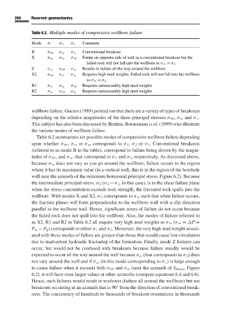
Table 6.2. Multiple modes of compressive wellbore failure
Mode σ 1 σ 2 σ 3 Comment
B σ θθ σ zz σ rr Conventional breakout
X σ zz σ rr σ θθ Forms on opposite side of well as a conventional breakout but the
failed rock will not fall into the wellbore as σ rr ≡ σ 2
Z σ zz σ θθ σ rr Results in failure all the way around the wellbore
X2 σ θθ σ rr σ zz Requires high mud weights. Failed rock will not fall into the wellbore
as σ rr ≡ σ 2
R1 σ rr σ zz σ θθ Requires unreasonably high mud weights
R2 σ rr σ θθ σ zz Requires unreasonably high mud weights
wellbore failure. Guenot (1989) pointed out that there are a variety of types of breakouts
depending on the relative magnitudes of the three principal stresses σ θθ , σ rr and σ v .
This subject has also been discussed by Bratton, Bornemann et al. (1999) who illustrate
the various modes of wellbore failure.
Table 6.2 summarizes six possible modes of compressive wellbore failure depending
upon whether σ θθ , σ rr or σ zz corresponds to σ 1 , σ 2 or σ 3 . Conventional breakouts
(referred to as mode B in the table), correspond to failure being driven by the magni-
tudes of σ θθ , and σ rr , that correspond to σ 1 and σ 3 , respectively. As discussed above,
because σ rr does not vary as you go around the wellbore, failure occurs in the region
where it has its maximum value (in a vertical well, this is in the region of the borehole
wall near the azimuth of the minimum horizontal principal stress, Figure 6.2). Because
the intermediate principal stress, σ 2 (σ 2 = σ zz in this case), is in the shear failure plane
when the stress concentration exceeds rock strength, the fractured rock spalls into the
wellbore. With modes X and X2, σ 2 corresponds to σ rr such that when failure occurs,
the fracture planes will form perpendicular to the wellbore wall with a slip direction
parallel to the wellbore wall. Hence, significant zones of failure do not occur because
the failed rock does not spall into the wellbore. Also, the modes of failure referred to
as X2, R1 and R2 in Table 6.2 all require very high mud weights as σ rr (σ rr ≡
P ≡
P m − P p ) corresponds to either σ 1 and σ 2 . Moreover, the very high mud weight associ-
ated with these modes of failure are greater than those that would cause lost circulation
due to inadvertent hydraulic fracturing of the formation. Finally, mode Z failures can
occur, but would not be confused with breakouts because failure usually would be
expected to occur all the way around the well because σ rr (that corresponds to σ 3 ) does
not vary around the well and if σ zz (in this mode corresponding to σ 1 )is large enough
to cause failure when it exceeds both σ θθ and σ rr (near the azimuth of S Hmax , Figure
6.2), it will have even larger values at other azimuths (compare equations 6.4 and 6.6).
Hence, such failures would result in washouts (failure all around the wellbore) but not
◦
breakouts occurring at an azimuth that is 90 from the direction of conventional break-
outs. The consistency of hundreds to thousands of breakout orientations in thousands