
Page 228 - Reservoir Geomechanics
P. 228
209 Determination of S 3 from mini-fracs
a.
HYDRAULIC FRACTURE
DIRECTION
LEAST PRINCIPAL
STRESS
LEAST PRINCIPAL STRESS
HYDRAULIC
FRACTURE
DIRECTION
b.
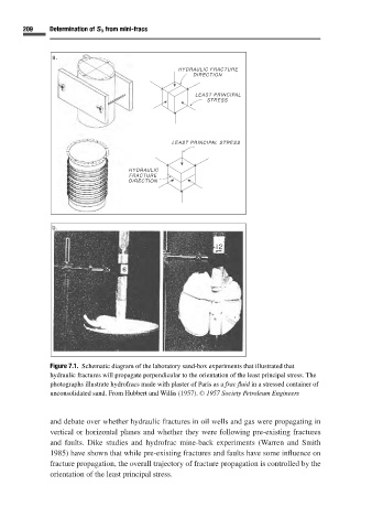
Figure 7.1. Schematic diagram of the laboratory sand-box experiments that illustrated that
hydraulic fractures will propagate perpendicular to the orientation of the least principal stress. The
photographs illustrate hydrofracs made with plaster of Paris as a frac fluid in a stressed container of
unconsolidated sand. From Hubbert and Willis (1957). C 1957 Society Petroleum Engineers
and debate over whether hydraulic fractures in oil wells and gas were propagating in
vertical or horizontal planes and whether they were following pre-existing fractures
and faults. Dike studies and hydrofrac mine-back experiments (Warren and Smith
1985)have shown that while pre-existing fractures and faults have some influence on
fracture propagation, the overall trajectory of fracture propagation is controlled by the
orientation of the least principal stress.