
Page 245 - Reservoir Geomechanics
P. 245
226 Reservoir geomechanics
138
124
110
97
S Hmax (MPa) 83
69
55
S v
41
28
28 41 55 69 83 97 110 124 138
S hmin (MPa)
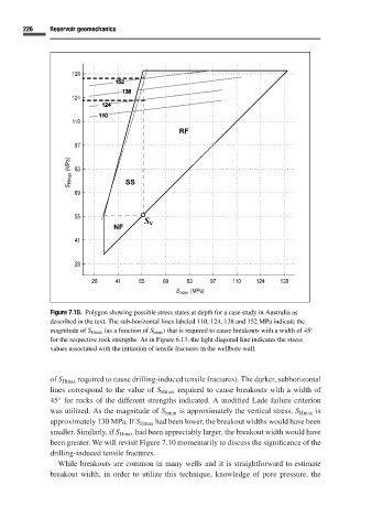
Figure 7.10. Polygon showing possible stress states at depth for a case study in Australia as
described in the text. The sub-horizontal lines labeled 110, 124, 138 and 152 MPa indicate the
magnitude of S Hmax (as a function of S hmin ) that is required to cause breakouts with a width of 45 ◦
for the respective rock strengths. As in Figure 6.13, the light diagonal line indicates the stress
values associated with the initiation of tensile fractures in the wellbore wall.
of S Hmax required to cause drilling-induced tensile fractures). The darker, subhorizontal
lines correspond to the value of S Hmax required to cause breakouts with a width of
45 for rocks of the different strengths indicated. A modified Lade failure criterion
◦
was utilized. As the magnitude of S hmin is approximately the vertical stress, S Hmax is
approximately 130 MPa. If S Hmax had been lower, the breakout widths would have been
smaller. Similarly, if S Hmax had been appreciably larger, the breakout width would have
been greater. We will revisit Figure 7.10 momentarily to discuss the significance of the
drilling-induced tensile fractures.
While breakouts are common in many wells and it is straightforward to estimate
breakout width, in order to utilize this technique, knowledge of pore pressure, the