
Page 244 - Reservoir Geomechanics
P. 244
225 Determination of S 3 from mini-fracs
Stress (bars)
0 500 1000 1500 2000
S Hmax
1 S hmin
2
Depth (km)
3
4
5 S
HYDROSTATIC hmin = 0.6S v S v
PORE PRESSURE
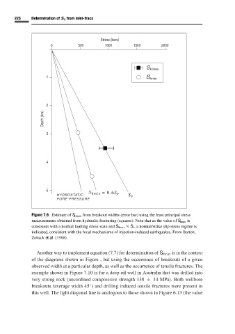
Figure 7.9. Estimate of S Hmax from breakout widths (error bar) using the least principal stress
measurements obtained from hydraulic fracturing (squares). Note that as the value of S hmin is
consistent with a normal faulting stress state and S Hmax ≈ S v ,a normal/strike slip stress regime is
indicated, consistent with the focal mechanisms of injection-induced earthquakes. From Barton,
Zoback et al.(1988).
Another way to implement equation (7.7) for determination of S Hmax is in the context
of the diagrams shown in Figure , but using the occurrence of breakouts of a given
observed width at a particular depth, as well as the occurrence of tensile fractures. The
example shown in Figure 7.10 is for a deep oil well in Australia that was drilled into
very strong rock (unconfined compressive strength 138 ± 14 MPa). Both wellbore
breakouts (average width 45 ) and drilling induced tensile fractures were present in
◦
this well. The light diagonal line is analogous to those shown in Figure 6.13 (the value