Page 256 - Reservoir Geomechanics
P. 256

237    Wellbore failure and stress determination in deviated wells


        a.                                b.                               X (North)
                                                                          d
                                                     y         y    r
                                                     s          b
                                                         X                    Y (East)
                       w                          s                 q
                                                  3
                                 s                          x
                                 tmin            s 1        s
                                                            Y
                                                                 x
                                                  s               b    f
                                                   2
                                                          z s
                     s
                      rr
                                                    Z
                     q
                                               Rotation Angle  Geographic  Stress
                                                 a
                                   s             b
                                    tmax
                                                                            z
                                                 g                    Z (Down)  b
        c.                                     d.
                               s tmax
        1.0
        0.5
                               s
               q tf1            tmin  q tf2
                               s rr
         0
            0    30   60   90  120  150  180
                        q, degree

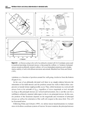
               Figure 8.1. (a) Stresses acting in the wall of an arbitrarily oriented well. (b) Coordinate system used
               to transform knowledge of principal stresses, to that around the wellbore. (c) Variation of principal
               stresses around an arbitrarily oriented wellbore. (d) Lower hemisphere projection used to display
               relative stability of wells with different deviations and azimuth. Modified from Peska and Zoback
               (1995).


               variations as a function of position around the well going clockwise from the bottom
               (Figure 8.1c).
                 In the case of an arbitrarily deviated well there is no simple relation between the
               orientation of far-field stresses and the position around the well at which either com-
               pressive or tensile failure might possibly occur. Thus, while breakouts in a vertical well
               always form at the azimuth of S hmin ,regardless of stress magnitude or rock strength
               (as long as the principal stresses are vertical and horizontal), this is not the case for a
               well that is arbitrarily oriented with respect to the in situ principal stresses. In this case,
               the position of the breakouts depends on the magnitude and orientation of principal
               stresses as well as the orientation of the well with respect to the stress field. This will
               be illustrated below.
                 Following Peska and Zoback (1995), we utilize tensor transformations to evaluate
               stress in the three coordinate systems of interest. In tensor notation, the principal stresses
   251   252   253   254   255   256   257   258   259   260   261