
Page 260 - Reservoir Geomechanics
P. 260
241 Wellbore failure and stress determination in deviated wells
a. b. c.
Normal Strike-Slip Reverse
S Hmax S Hmax S Hmax
Sv Sv Sv
S hmin
S hmin
S hmin
35 40 45 50 55 60 65 35 40 45 50 55 60 65
Required P m 35 40 45 50 55 60 65
T 0 = 0 Required P m Required P m
T 0 = 0 T 0 = 0
S = 55 MPa S = 105 MPa
Hmax Hmax S Hmax = 145 MPa
S hmin = 45 MPa S hmin = 55 MPa = 125 MPa
S hmin
S = 70 MPa S = 70 MPa
v v S = 70 MPa
v
P p = 32 MPa P p = 32 MPa = 32 MPa
P p
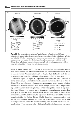
Figure 8.3. The tendency for the initiation of tensile fractures to form in wells of different
orientation for normal, strike-slip and reverse faulting stress regimes. Similar to the figures in Peska
and Zoback (1995). The magnitudes of the stresses, pore pressure and mud weight assumed for
each case is shown. Note that the color indicates the mud pressure required to initiate tensile
failure. Hence red indicates that tensile fractures are likely to form as little excess mud weight is
required to initiate failure whereas blue indicates the opposite.
stable in normal faulting regimes. Second, it should also be noted that these figures
were constructed for the initiation of breakouts, not the severity of breakouts, which
is addressed below. As discussed at length in Chapter 10,to drill stable wells it is not
necessary to prevent breakout initiation; it is necessary to limit breakout severity.
Similar to Figure 8.2, Figure 8.3 represents the tendency for tensile fractures to
occur. In this case, the assumed stress states and pore pressure are identical to those in
Figure 8.2,but the colors now indicate the magnitude of mud weight required to induce
tensile failure of the wellbore wall. Zero tensile strength was assumed although assum-
ing a finite value of tensile strength would not have changed the results in any signif-
icant way. When drilling-induced tensile fractures are expected at mud weights close
to the pore pressure, the figures are shaded red. When extremely high mud weights are
required to initiate tensile fractures, the figures are shaded dark blue. In the cases for
normal and strike-slip faulting (Figures 8.3a,b), the darkest blue corresponds to mud
weights in excess of the least principal stress, which could likely not be achieved prior
to losing circulation. Note that in strike-slip faulting areas (Figure 8.3b), all wells devi-
◦
ated less than 30 are expected to have drilling-induced tensile fractures, as previously