
Page 262 - Reservoir Geomechanics
P. 262
243 Wellbore failure and stress determination in deviated wells
a.
"Looking down the hole" "Borehole image"
Orientation of breakouts Azi = 0; Dev = 60 Bottom Top Bottom
Depth
Bottom
posBO = 26 posBO
b.
"Looking down the hole" "Borehole image"
Orientation of fractures Azi = 0; Dev = 60 Bottom Top Bottom
Depth
incTF = 63
posTF = 137
Bottom
posTF
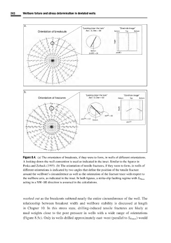
Figure 8.4. (a) The orientation of breakouts, if they were to form, in wells of different orientations.
A looking-down-the-well convention is used as indicated in the inset. Similar to the figures in
Peska and Zoback (1995). (b) The orientation of tensile fractures, if they were to form, in wells of
different orientations is indicated by two angles that define the position of the tensile fracture
around the wellbore’s circumference as well as the orientation of the fracture trace with respect to
the wellbore axis, as indicated in the inset. In both figures, a strike-slip faulting regime with S Hmax
acting in a NW–SE direction is assumed in the calculations.
washed out as the breakouts subtend nearly the entire circumference of the well. The
relationship between breakout width and wellbore stability is discussed at length
in Chapter 10.In this stress state, drilling-induced tensile fractures are likely at
mud weights close to the pore pressure in wells with a wide range of orientations
(Figure 8.5c). Only in wells drilled approximately east–west (parallel to S Hmax )would