
Page 263 - Reservoir Geomechanics
P. 263
244 Reservoir geomechanics
a. b.
Tendency for breakouts Orientation of breakouts
100 120 140 160 180
Breakout width (w BO )
c. Tendency for fractures d. Orientation of fractures
40 60 80 100 120 140
Required P m
T 0 = 0
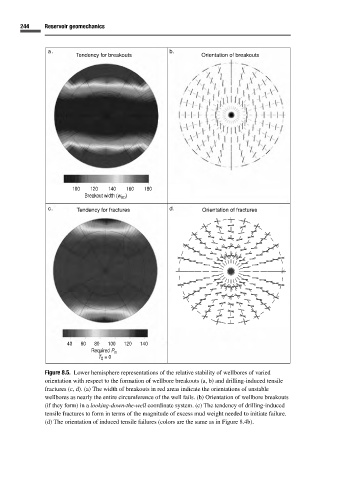
Figure 8.5. Lower hemisphere representations of the relative stability of wellbores of varied
orientation with respect to the formation of wellbore breakouts (a, b) and drilling-induced tensile
fractures (c, d). (a) The width of breakouts in red areas indicate the orientations of unstable
wellbores as nearly the entire circumference of the well fails. (b) Orientation of wellbore breakouts
(if they form) in a looking-down-the-well coordinate system. (c) The tendency of drilling-induced
tensile fractures to form in terms of the magnitude of excess mud weight needed to initiate failure.
(d) The orientation of induced tensile failures (colors are the same as in Figure 8.4b).