
Page 264 - Reservoir Geomechanics
P. 264
245 Wellbore failure and stress determination in deviated wells
a. Conductivity b. Conductivity
Low High Low High
0 90 180 270 360 0 90 180 270 360
3253.7
3213.2
3253.8
Depth (meters) 3253.9 3213.3
3254.0 3213.4
Natural
3254.1 3213.5 Induced
Natural
3254.2
3213.6
Induced Induced Induced
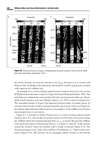
Figure 8.6. Electrical resistivity image of drilling-induced tensile fractures observed in the KTB
pilot hole (after Peska and Zoback 1995).
the tensile fractures be axial and oriented at the S Hmax direction as in a vertical well
(Figure 8.5d). At all other well orientations, the fractures would be significantly inclined
with respect to the wellbore axis.
An example of en echelon drilling-induced tensile fractures observed in the vertical
KTB pilot hole in Germany is shown in Figure 8.6b (after Peska and Zoback 1995). The
pilot hole was continuously cored and these fractures are not present in the core. Nearly
all the tensile fractures were axial (Brudy, Zoback et al. 1997)as shown in Figure 8.6a.
The sinusoidal features in Figure 8.6a represent foliation planes in granitic gneiss. In
intervalswherethestressfieldislocallyperturbedbysliponactivefaults(seeChapter9),
the drilling-induced fractures that form occur at an angle ω to the wellbore axis because
one principal stress is not vertical.
Figure 8.7 is intended to better illustrate how en echelon drilling-induced tensile
fractures form. It is obvious that the tensile fracture will first form at the point around
the wellbore where the minimum principal stress, σ tmin ,is tensile. Because the wellbore
◦
◦
is deviated with respect to the principal stresses, ω is about 15 and 165 in the sections
around the wellbore where the borehole wall is locally in tension (Figure 8.7a). The
fractures propagate over a span of the wellbore circumference, θ t , where tensile stress
exists (Figure 8.7b). The fractures do not propagate further because as the fracture