Page 279 - Reservoir Geomechanics
P. 279

260    Reservoir geomechanics


               a. Borehole geometry
                                  North

                              a

                                    East


                        I


                               Apparent fast
                               direction plane


                     Down

               b. Stress geometry                c. Structural geometry
                                     North                                   North


                                        East                                      East
                                 S Hmax                                    f a
                                                  True fast
                                                 dip direction  f d


                          Fast
                                                           Fn


                                                              Fast
                                                              plane


                                                                Down
                     Down
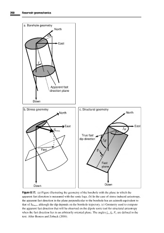
              Figure 8.17. (a) Figure illustrating the geometry of the borehole with the plane in which the
              apparent fast direction is measured with the sonic logs. (b) In the case of stress-induced anisotropy,
              the apparent fast direction in the plane perpendicular to the borehole has an azimuth equivalent to
              that of S Hmax , although the dip depends on the borehole trajectory. (c) Geometry used to compute
              the apparent fast direction that will be observed on the dipole sonic tool for structural anisotropy
              when the fast direction lies in an arbitrarily oriented plane. The angles f α , f d , F n are defined in the
              text. After Boness and Zoback (2006).
   274   275   276   277   278   279   280   281   282   283   284