
Page 278 - Reservoir Geomechanics
P. 278
259 Wellbore failure and stress determination in deviated wells
a. b.
Plane normal Plane normal
to borehole to borehole
Fast
Fast
Fast Fast
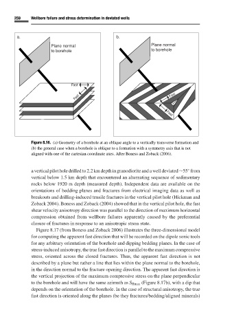
Figure 8.16. (a) Geometry of a borehole at an oblique angle to a vertically transverse formation and
(b) the general case when a borehole is oblique to a formation with a symmetry axis that is not
aligned with one of the cartesian coordinate axes. After Boness and Zoback (2006).
avertical pilot holedrilled to2.2kmdepthingranodioriteandawelldeviated ∼55 from
◦
vertical below 1.5 km depth that encountered an alternating sequence of sedimentary
rocks below 1920 m depth (measured depth). Independent data are available on the
orientations of bedding planes and fractures from electrical imaging data as well as
breakouts and drilling-induced tensile fractures in the vertical pilot hole (Hickman and
Zoback 2004). Boness and Zoback (2004) showed that in the vertical pilot hole, the fast
shear velocity anisotropy direction was parallel to the direction of maximum horizontal
compression obtained from wellbore failures apparently caused by the preferential
closure of fractures in response to an anisotropic stress state.
Figure 8.17 (from Boness and Zoback 2006) illustrates the three-dimensional model
for computing the apparent fast direction that will be recorded on the dipole sonic tools
for any arbitrary orientation of the borehole and dipping bedding planes. In the case of
stress-induced anisotropy, the true fast direction is parallel to the maximum compressive
stress, oriented across the closed fractures. Thus, the apparent fast direction is not
described by a plane but rather a line that lies within the plane normal to the borehole,
in the direction normal to the fracture opening direction. The apparent fast direction is
the vertical projection of the maximum compressive stress on the plane perpendicular
to the borehole and will have the same azimuth as S Hmax (Figure 8.17b), with a dip that
depends on the orientation of the borehole. In the case of structural anisotropy, the true
fast direction is oriented along the planes (be they fractures/bedding/aligned minerals)