
Page 273 - Reservoir Geomechanics
P. 273
254 Reservoir geomechanics
a. b. c.
0 40 80 120 160 200 240 280 320 360
XXX.9 0 180 360
60 2900
50
w
40
30
s min 20 s tmin 2901
10
XXX.2
0
−10
0 90 180 270 360
2902
q t q t
XXX.5
2903
XXX.8
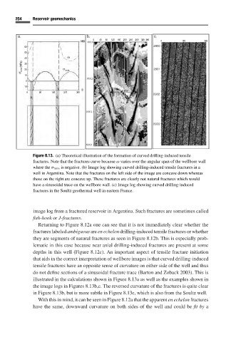
Figure 8.13. (a) Theoretical illustration of the formation of curved drilling-induced tensile
fractures. Note that the fractures curve because ω varies over the angular span of the wellbore wall
where the σ tmin is negative. (b) Image log showing curved drilling-induced tensile fractures in a
well in Argentina. Note that the fractures on the left side of the image are concave down whereas
those on the right are concave up. These fractures are clearly not natural fractures which would
have a sinusoidal trace on the wellbore wall. (c) Image log showing curved drilling-induced
fractures in the Soultz geothermal well in eastern France.
image log from a fractured reservoir in Argentina. Such fractures are sometimes called
fish-hook or J-fractures.
Returning to Figure 8.12a one can see that it is not immediately clear whether the
fractures labeled ambiguous are en echelon drilling-induced tensile fractures or whether
they are segments of natural fractures as seen in Figure 8.12b. This is especially prob-
lematic in this case because near axial drilling-induced fractures are present at some
depths in this well (Figure 8.12c). An important aspect of tensile fracture initiation
that aids in the correct interpretation of wellbore images is that curved drilling-induced
tensile fractures have an opposite sense of curvature on either side of the well and thus
do not define sections of a sinusoidal fracture trace (Barton and Zoback 2003). This is
illustrated in the calculations shown in Figure 8.13aas well as the examples shown in
the image logs in Figures 8.13b,c. The reversed curvature of the fractures is quite clear
in Figure 8.13b, but is more subtle in Figure 8.13c, which is also from the Soultz well.
With this in mind, it can be seen in Figure 8.12a that the apparent en echelon fractures
have the same, downward curvature on both sides of the well and could be fit by a