
Page 30 - Reservoir Geomechanics
P. 30
15 The tectonic stress field
The orientation of the principal stresses is determined from wellbore obser-
vations (Chapter 6), recent geologic indicators and earthquake focal mechanisms
(Chapter 5).
S 3 (which corresponds to S hmin ,except in reverse faulting regimes) is obtained from
mini-fracs and leak-off tests (Chapter 6).
Pore pressure, P p ,is either measured directly or estimated from geophysical logs or
seismic data (Chapter 2).
With these parameters constrained, it is only necessary to constrain S Hmax in order
to have a reliable estimate of the complete stress tensor as part of a comprehensive
geomechanical model of the subsurface. Constraints on the frictional strength of the
crust (discussed in Chapter 4) provide general bounds on S Hmax (as a function of
depth and pore pressure). Having observations of wellbore failures (breakouts and
drilling-induced tensile fractures) allows for much more precise estimates of S Hmax .
This is discussed for vertical wells in Chapter 7 and for deviated and horizontal wells
in Chapter 8.
This strategy for in situ stress measurement at depth was first employed to estimate
the magnitude of the three principal stresses in the Cajon Pass and KTB (Kontinen-
tale Tiefbohrprogramm der Bundesrepublik Deutschland) scientific drilling projects
(Zoback and Healy 1992; Zoback, Apel et al. 1993; Brudy, Zoback et al. 1997) and
is referred to as an integrated stress measurement strategy as it utilizes a wide variety
of observations (Zoback, Barton et al. 2003). Geomechanical models determined with
these techniques appear in the case histories discussed in Chapters 9–12.Table 1.2
provides an overview of horizontal principal stress determination methods discussed
in the chapters that follow.
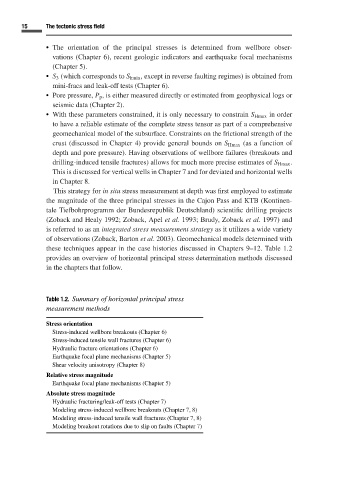
Table 1.2. Summary of horizontal principal stress
measurement methods
Stress orientation
Stress-induced wellbore breakouts (Chapter 6)
Stress-induced tensile wall fractures (Chapter 6)
Hydraulic fracture orientations (Chapter 6)
Earthquake focal plane mechanisms (Chapter 5)
Shear velocity anisotropy (Chapter 8)
Relative stress magnitude
Earthquake focal plane mechanisms (Chapter 5)
Absolute stress magnitude
Hydraulic fracturing/leak-off tests (Chapter 7)
Modeling stress-induced wellbore breakouts (Chapter 7, 8)
Modeling stress-induced tensile wall fractures (Chapter 7, 8)
Modeling breakout rotations due to slip on faults (Chapter 7)