
Page 133 - Robot Builder's Bonanza
P. 133
102 BUILD A MOTORIZED PLASTIC PLATFORM
Cutouts for
wheels
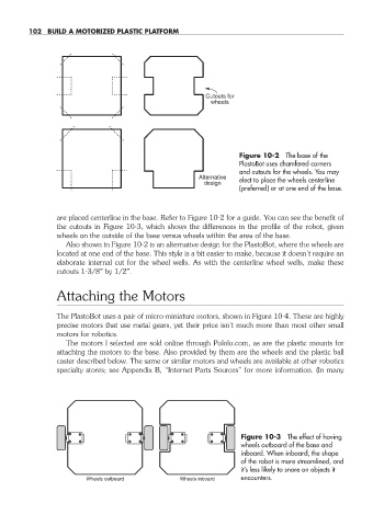
Figure 10-2 The base of the
PlastoBot uses chamfered corners
and cutouts for the wheels. You may
Alternative
design elect to place the wheels centerline
(preferred) or at one end of the base.
are placed centerline in the base. Refer to Figure 10-2 for a guide. You can see the benefit of
the cutouts in Figure 10-3, which shows the differences in the profile of the robot, given
wheels on the outside of the base versus wheels within the area of the base.
Also shown in Figure 10-2 is an alternative design for the PlastoBot, where the wheels are
located at one end of the base. This style is a bit easier to make, because it doesn’t require an
elaborate internal cut for the wheel wells. As with the centerline wheel wells, make these
cutouts 1-3/8″ by 1/2″.
Attaching the Motors
The PlastoBot uses a pair of micro- miniature motors, shown in Figure 10-4. These are highly
precise motors that use metal gears, yet their price isn’t much more than most other small
motors for robotics.
The motors I selected are sold online through Pololu.com, as are the plastic mounts for
attaching the motors to the base. Also provided by them are the wheels and the plastic ball
caster described below. The same or similar motors and wheels are available at other robotics
specialty stores; see Appendix B, “Internet Parts Sources” for more information. (In many
Figure 10-3 The effect of having
wheels outboard of the base and
inboard. When inboard, the shape
of the robot is more streamlined, and
it’s less likely to snare on objects it
Wheels outboard Wheels inboard encounters.
10-chapter-10.indd 102 4/21/11 11:45 AM