
Page 134 - Robot Builder's Bonanza
P. 134
ATTACHING THE MOTORS 103
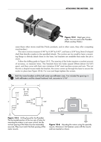
Figure 10-4 Metal gear micro
motor. Two are used in the PlastoBot.
(Photo courtesy Pololu.)
cases these other stores resell the Pololu products, and in other cases, they offer competing
merchandise.)
The micro motors measure 0.94″ by 0.39″ by 0.47″, and have a 3/8″-long 3mm D- shaped
shaft that directly couples to the specified wheels. The motors are too small to have a mount-
ing flange to directly attach them to the base, but brackets are available that make the job a
cinch.
Follow the drilling guide in Figure 10-5. The spacing of the holes requires a modest amount
of accuracy, so measure twice. The brackets have two holes spaced 18mm (about 11/16″)
apart, and they come with their own miniature 2-56″ steel machine screws and nuts. The nut
fits into a shaped recess inside the bracket; the screw comes up through the base to secure the
motor in place (see Figure 10-6). For now just finger- tighten the screws.
G Both the motor brackets and the ball caster use millimeter sizes. I’ve included the spacings in
both millimeters and the closest fractional inch, accurate to 1/16″.
4"
3/16"
9/16"
(15mm)
Bracket
11/16"
4" (18mm) 1-3/8"
Motor
1/2"
Base
Figure 10-5 Drilling layout for the PlastoBot.
The horizontal position of the two sets of holes for
mounting the motors is not super critical, but the
vertical spacing of the holes must be reasonably Figure 10-6 Mounting the motors using the specialty
accurate. They must match the hole spacing of the mounts. Miniature 2-56 fasteners come with the mounts
motor mounts. and are inserted as shown.
10-chapter-10.indd 103 4/21/11 11:45 AM