Page 156 - Robot Builder's Bonanza
P. 156

MAKING THE BASE    125


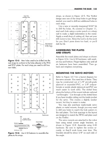
                          Use this                     straps, as shown in Figure 12-5. The TinBot
                         existing hole
                                                       design uses one of the strap holes to get things
                                                       started; you need to drill two additional holes in
                                                       each strap.
                                                         Use a new or recently sharpened 9/64″ bit
                                                       to drill the holes. As covered in Chapter 11,
                  2-5/8"                               start each hole using a center punch or a sharp
                                                       nail to make a slight indentation in the metal.
                                                       Apply a small drop of cutting oil, then set your
                                                       drill motor to low. Allow the tool to do the work
                                                       for you. Don’t press down too hard, or you’ll
                          Drill
                                             Drill second  dull the bit.
                  2-1/8"                     strap, but in
                          Drill              mirror image
                                                       ASSEMBLING THE PLATES
                                                       AND STRAPS
                                                       Assemble the metal plates and straps as shown
                                                       in Figure 12-6. Use 6-32 hardware, with wash-
           Figure 12-5  New holes need to be drilled into the   ers top and bottom.  Finger- tighten only until all
           nail straps to conform to the holes already in the TP35
           and TP37 plates. For each strap you need to drill two   six fasteners have been assembled. Then go
           new holes.                                  back and retighten everything.

                                                       MOUNTING THE SERVO MOTORS
                                                       Refer to Figure 12-7 for a layout diagram for
                                                       the servo mounts. You need two of these. They
                                                       may be constructed out of 1/4″  aircraft- grade
                                                       plywood or expanded PVC, or 1/8″ polycar-
                                                       bonate or acrylic plastic (plywood and PVC are
                                                       much easier to work with). The dotted lines
                                                       along the bottom of the mount indicate optional
                                                         “cut- throughs.” Cut through at the dotted lines
                                                       if you have trouble cutting out the inside pocket
                                                       for the servo. This creates a slightly weaker
                                                       mount, but they’re easier to make.
                                                         You may also purchase  ready- made servo
                                                       plastic or metal mounts, though you may need
                                                       to drill new holes to match the hole pattern in
                                                       the nail plates. The hole spacings in the layout
                                           Fasteners   are designed to match the TP35 nail plate used
                                                       on the TinBot.
                         6-32 x 3/8"
                        machine screw                    The servo mounts are attached to the robot
                                     Assembled
                 Washer                                base using metal corner angle brackets, as
                            Plate                      shown in Figure 12-8. Assemble using 4-40
                 Strap
                         Washer                        hardware. Be sure to tighten the screws se-
                 6-32 nut                                curely, or they’ll work loose over time. The
           Figure 12-6  Use 6-32 fasteners to assemble the   brackets should be about 3/4″ on each side of
           plates to the straps.                       the angle.


 12-chapter-12.indd   125                                                                   4/21/11   11:46 AM
   151   152   153   154   155   156   157   158   159   160   161