
Page 157 - Robot Builder's Bonanza
P. 157
126 BUILD A MOTORIZED METAL PLATFORM
4-40 x 1/2"
machine screw
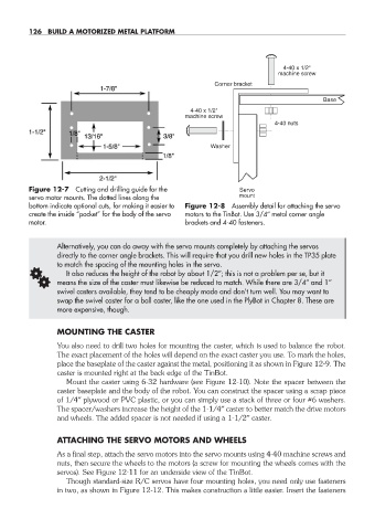
Corner bracket
Base
4-40 x 1/2"
machine screw
4-40 nuts
Washer
Figure 12-7 Cutting and drilling guide for the Servo
servo motor mounts. The dotted lines along the mount
bottom indicate optional cuts, for making it easier to Figure 12-8 Assembly detail for attaching the servo
create the inside “pocket” for the body of the servo motors to the TinBot. Use 3/4″ metal corner angle
motor. brackets and 4-40 fasteners.
Alternatively, you can do away with the servo mounts completely by attaching the servos
directly to the corner angle brackets. This will require that you drill new holes in the TP35 plate
to match the spacing of the mounting holes in the servo.
G means the size of the caster must likewise be reduced to match. While there are 3/4″ and 1″
It also reduces the height of the robot by about 1/2″; this is not a problem per se, but it
swivel casters available, they tend to be cheaply made and don’t turn well. You may want to
swap the swivel caster for a ball caster, like the one used in the PlyBot in Chapter 8. These are
more expensive, though.
MOUNTING THE CASTER
You also need to drill two holes for mounting the caster, which is used to balance the robot.
The exact placement of the holes will depend on the exact caster you use. To mark the holes,
place the baseplate of the caster against the metal, positioning it as shown in Figure 12-9. The
caster is mounted right at the back edge of the TinBot.
Mount the caster using 6-32 hardware (see Figure 12-10). Note the spacer between the
caster baseplate and the body of the robot. You can construct the spacer using a scrap piece
of 1/4″ plywood or PVC plastic, or you can simply use a stack of three or four #6 washers.
The spacer/washers increase the height of the 1-1/4″ caster to better match the drive motors
and wheels. The added spacer is not needed if using a 1-1/2″ caster.
ATTACHING THE SERVO MOTORS AND WHEELS
As a final step, attach the servo motors into the servo mounts using 4-40 machine screws and
nuts, then secure the wheels to the motors (a screw for mounting the wheels comes with the
servos). See Figure 12-11 for an underside view of the TinBot.
Though standard- size R/C servos have four mounting holes, you need only use fasteners
in two, as shown in Figure 12-12. This makes construction a little easier. Insert the fasteners
12-chapter-12.indd 126 4/21/11 11:46 AM