
Page 158 - Robot Builder's Bonanza
P. 158
USING THE TINBOT 127
Caster
base plate
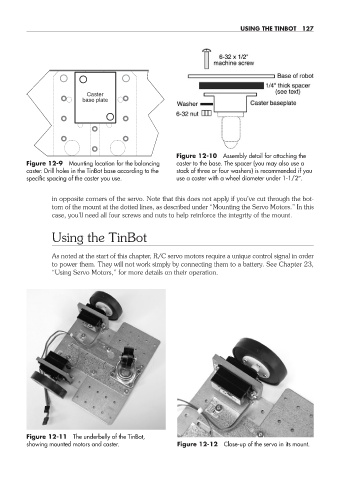
Figure 12-10 Assembly detail for attaching the
Figure 12-9 Mounting location for the balancing caster to the base. The spacer (you may also use a
caster. Drill holes in the TinBot base according to the stack of three or four washers) is recommended if you
specific spacing of the caster you use. use a caster with a wheel diameter under 1-1/2″.
in opposite corners of the servo. Note that this does not apply if you’ve cut through the bot-
tom of the mount at the dotted lines, as described under “Mounting the Servo Motors.” In this
case, you’ll need all four screws and nuts to help reinforce the integrity of the mount.
Using the TinBot
As noted at the start of this chapter, R/C servo motors require a unique control signal in order
to power them. They will not work simply by connecting them to a battery. See Chapter 23,
“Using Servo Motors,” for more details on their operation.
Figure 12-11 The underbelly of the TinBot,
showing mounted motors and caster. Figure 12-12 Close- up of the servo in its mount.
12-chapter-12.indd 127 4/21/11 11:46 AM