
Page 204 - Robot Builder's Bonanza
P. 204
EXPERIMENTING WITH “NO- CUT” METAL PLATFORM DESIGNS 173
mounted at the base. The Tamiya caster offers the option of two heights; I selected the taller
height to better match the wheelbase afforded by the motors and tires.
Only a few holes need be drilled in the strapping T. I used a 5/32″ drill to make holes for
4-40 1/4″ machine screws. The small fasteners and the somewhat larger holes provide
some “slop” in mounting. With some wiggle room, you can better align the caster (not critical)
and the two motors (critical).
Total weight of the Mini T- bot prototype, with 66T strapping T, motors, wheels, caster,
battery holder, battery, 25- column breadboard, and assorted small switches, is 17.5 ounces
(that’s 496 grams for you metric folks). Note that the four AA batteries alone contribute 3.5
ounces (about 100 grams) to the weight of the robot.
For your reference, here are the specifications of the most commonly available sizes of
Simpson Strong- Tie strapping Ts, and their weight in ounces and grams. Larger robots can
be built using bigger strapping Ts. The 1212T strap weighs almost a pound, so you need big-
ger motors (and batteries) to haul around that kind of weight.
Model Material L H W* Weight
66T 14-gauge galvanized 6″ 5″ 1-1/2″ 5 oz; 142 g
128T 14-gauge galvanized 12″ 8″ 2″ 11 oz; 312 g
1212T 14-gauge galvanized 12″ 12″ 2″ 14 oz; 397 g
* W is the width of the strapping metal.
USING LARGER Ts FOR LARGER BOTS
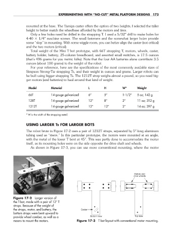
The robot brute in Figure 17-2 uses a pair of 1212T straps, separated by 5″-long aluminum
tubing used as “risers.” In this particular prototype, the motors were mounted at an angle,
with the metal of the lower T bent at 45°. This was partly done to accommodate the motor
itself, as its mounting holes were on the side opposite the drive shaft and wheels.
As shown in Figure 17-3, you can use more conventional mounting, where the motor
Motors and
drive wheels
Figure 17-2 Larger version of
the T- bot, made with a pair of 12″ T
straps. Because of the weight of
the straps, motor, and battery, the Caster
bottom straps were bent upward to
provide wheel camber, as well as a Bottom view Top view
means to mount the motors. Figure 17-3 T- bot layout with conventional motor mounting.
17-chapter-17.indd 173 4/21/11 11:49 AM