
Page 283 - Robot Builder's Bonanza
P. 283
252 USING SERVO MOTORS
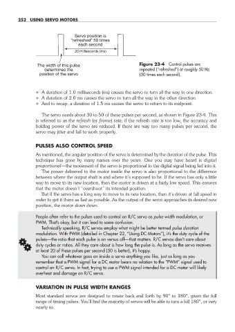
Servo position is
"refreshed" 50 times
each second
20 milliseconds (ms)
The width of this pulse Figure 23- 4 Control pulses are
determines the repeated (“refreshed”) at roughly 50 Hz
position of the servo (50 times each second).
• A duration of 1.0 milliseconds (ms) causes the servo to turn all the way in one direction.
• A duration of 2.0 ms causes the servo to turn all the way in the other direction.
• And to recap, a duration of 1.5 ms causes the servo to return to its midpoint.
The servo needs about 30 to 50 of these pulses per second, as shown in Figure 23- 4. This
is referred to as the refresh (or frame) rate; if the refresh rate is too low, the accuracy and
holding power of the servo are reduced. If there are way too many pulses per second, the
servo may jitter and fail to work properly.
PULSES ALSO CONTROL SPEED
As mentioned, the angular position of the servo is determined by the duration of the pulse. This
technique has gone by many names over the years. One you may have heard is digital
proportional— the movement of the servo is proportional to the digital signal being fed into it.
The power delivered to the motor inside the servo is also proportional to the difference
between where the output shaft is and where it’s supposed to be. If the servo has only a little
way to move to its new location, then the motor is driven at a fairly low speed. This ensures
that the motor doesn’t “overshoot” its intended position.
But if the servo has a long way to move to its new location, then it’s driven at full speed in
order to get it there as fast as possible. As the output of the servo approaches its desired new
position, the motor slows down.
People often refer to the pulses used to control an R/C servo as pulse width modulation, or
PWM. That’s okay, but it can lead to some confusion.
Technically speaking, R/C servos employ what might be better termed pulse duration
modulation. With PWM (detailed in Chapter 22, “Using DC Motors”), it’s the duty cycle of the
G pulses— the ratio that each pulse is on versus off— that matters. R/C servos don’t care about
duty cycles or ratios. All they care about is how long the pulse is. As long as the servo receives
at least 20 of these pulses per second (50 is better), it’s happy.
You can call whatever goes on inside a servo anything you like, just as long as you
remember that a PWM signal for a DC motor bears no relation to the “PWM” signal used to
control an R/C servo. In fact, trying to use a PWM signal intended for a DC motor will likely
overheat and damage an R/C servo.
VARIATION IN PULSE WIDTH RANGES
Most standard servos are designed to rotate back and forth by 90° to 180°, given the full
range of timing pulses. You’ll find the majority of servos will be able to turn a full 180°, or very
nearly so.
23-chapter-23.indd 252 4/21/11 11:51 AM