
Page 281 - Robot Builder's Bonanza
P. 281
250 USING SERVO MOTORS
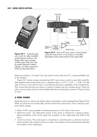
Figure 23- 2 How an RC servo works. A control signal
Figure 23- 1 A standard- size causes the motor to turn in one direction or the other,
servo motor for radio- controlled depending on the current position of the output shaft.
model airplanes and cars. The
flanges allow easy mounting,
and the output of the servo can
be readily attached to wheels,
linkages, and other mechanisms.
(Photo courtesy Hitec RCD.)
(unless you want to, of course). You can control a servo with your PC, a microcontroller such
as the Arduino.
Figure 23- 1 shows a typical standard- size R/C servo motor, which is used with model fly-
able airplanes and model racing cars. It measures about 1- 1/2″ 3/4″ 1- 3/8″. For this
style of servo, its size and the way it’s mounted are the same, regardless of the manufacturer.
That means that you have your pick of a variety of makers and can compare prices. There are
other common sizes of servo motors besides that shown in the figure, however. I’ll get to those
in a bit.
A PEEK INSIDE
Inside the servo is a motor and various other components, neatly packaged (see Figure 23- 2).
While not all servos are exactly alike, all have these three major parts: motor, reduction gear,
and control circuitry.
• Motor. A DC motor capable of reversing direction is at the heart of the servo.
• Reduction gears. The high- speed output of the motor is reduced by a gearing system.
Many revolutions of the motor equal one revolution of the output gear and shaft of the
servo.
• Control circuitry. The output gear is connected to a potentiometer, a common electronic
device similar to the volume control on a radio. The position of the potentiometer indicates
the position of the output gear.
23-chapter-23.indd 250 4/21/11 11:51 AM