
Page 277 - Robot Builder's Bonanza
P. 277
246 USING DC MOTORS
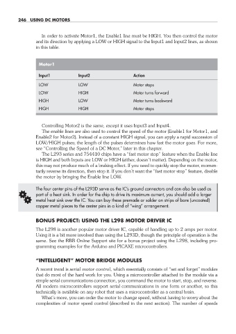
In order to activate Motor1, the Enable1 line must be HIGH. You then control the motor
and its direction by applying a LOW or HIGH signal to the Input1 and Input2 lines, as shown
in this table.
Motor1
Input1 Input2 Action
LOW LOW Motor stops
LOW HIGH Motor turns forward
HIGH LOW Motor turns backward
HIGH HIGH Motor stops
Controlling Motor2 is the same, except it uses Input3 and Input4.
The enable lines are also used to control the speed of the motor (Enable1 for Motor1, and
Enable2 for Motor2). Instead of a constant HIGH signal, you can apply a rapid succession of
LOW/HIGH pulses; the length of the pulses determines how fast the motor goes. For more,
see “Controlling the Speed of a DC Motor,” later in this chapter.
The L293 series and 754410 chips have a “fast motor stop” feature when the Enable line
is HIGH and both Inputs are LOW or HIGH (either, doesn’t matter). Depending on the motor,
this may not produce much of a braking effect. If you need to quickly stop the motor, momen-
tarily reverse its direction, then stop it. If you don’t want the “fast motor stop” feature, disable
the motor by bringing the Enable line LOW.
The four center pins of the L293D serve as the IC’s ground connectors and can also be used as
G part of a heat sink. In order for the chip to drive its maximum current, you should add a larger
metal heat sink over the IC. You can buy these premade or solder on strips of bare (uncoated)
copper metal pieces to the center pins in a kind of “wing” arrangement.
BONUS PROJECT: USING THE L298 MOTOR DRIVER IC
The L298 is another popular motor driver IC, capable of handling up to 2 amps per motor.
Using it is a bit more involved than using the L293D, though the principle of operation is the
same. See the RBB Online Support site for a bonus project using the L298, including pro-
gramming examples for the Arduino and PICAXE microcontrollers.
“INTELLIGENT” MOTOR BRIDGE MODULES
A recent trend is serial motor control, which essentially consists of “set and forget” modules
that do most of the hard work for you. Using a microcontroller attached to the module via a
simple serial communications connection, you command the motor to start, stop, and reverse.
All modern microcontrollers support serial communications in one form or another, so this
technically is available on any robot that uses a microcontroller as a central brain.
What’s more, you can order the motor to change speed, without having to worry about the
complexities of motor speed control (described in the next section). The number of speeds
22-chapter-22.indd 246 4/21/11 11:50 AM